Apparatus and method for steering a belt

a belt and accessory technology, applied in the field of accessory for steering a belt, can solve the problems of increasing the risk of belt damage during operation, reducing the lateral and requiring a running belt to operate the steering mechanism, so as to reduce the risk of belt buckling, the effect of sufficiently supporting and minimizing the distance between the rotatable element and the steering roller

Inactive Publication Date: 2010-10-05
OCE TECH
View PDF11 Cites 14 Cited by
  • Summary
  • Abstract
  • Description
  • Claims
  • Application Information

AI Technical Summary

Benefits of technology

[0013]Another advantage of the present invention is that the lateral distance between the rotatable element and the steering roller is minimized and constant, so the belt is sufficiently supported at all times during operation, which limits the risk of buckling of the belt. Rotation of the rotatable element is induced by frictional forces upon contact with a side portion of the belt. Small lateral deviations from the desired path of the belt are corrected and the path of the belt is accurately controlled within a narrow range of lateral positions, with very small forces exercised by the belt on the rotatable element.
[0014]An additional advantage of the present invention is that the mechanism is simple and compact.
[0015]In an embodiment, the rotatable element is a freely rotatable element. The freely rotatable element is rotatable about the third axis, independently from the rotation of the steering roller about the first axis. Rotation of the freely rotatable element is induced by a frictional force between a side portion of the belt and the freely rotatable element, if the belt touches the rotatable element.
[0016]In an embodiment, the first axis and the third axis coincide, such that the rotatable element and the steering roller are axially aligned. This configuration has the advantage that it enables a relatively simple and compact transfer mechanism for transferring the rotational motion of the rotatable element into a pivoting motion of the steering roller.
[0017]In an embodiment, the dimension of at least a portion of the rotatable element extending from the third axis to the perimeter of the rotatable element, perpendicular to the third axis, exceeds the radius of the steering roller. This arrangement enables contact between a side portion of the belt and the rotatable element. It is recognized that a simple representation of the above-described rotatable element is a circular flange, having a diameter that is larger than the diameter of the steering roller and having coinciding first and third axes.
[0018]In an embodiment, the rotatable element is arranged at a first axial end portion of the steering roller. The rotatable element and the steering roller are axially aligned. This arrangement provides a fully supported belt (supported by the steering roller) that upon contact with the freely rotatable element is able to induce a relatively large torque with a small frictional force without the risk of buckling of the belt.

Problems solved by technology

Although the apparatus known from the cited reference enables steering of a belt to its desired path, it has the disadvantage that relatively large steering forces and hence large frictional forces between the rotatable element and the side portion of the running belt are required to operate the steering mechanism.
A large contact area between the rotatable element and the belt increases the risk of damaging the belt during operation.
Practice has shown that, unlike for relatively long belts, the running path of relatively short belts is extremely sensitive towards torsion of the frame that holds the rollers that support the belt.
Therefore, short belts cannot be steered in this way.
Short belts run off the rollers and get damaged beyond repair.

Method used


Image

  • Apparatus and method for steering a belt
  • Apparatus and method for steering a belt
  • Apparatus and method for steering a belt

Examples


Embodiment Construction

[0041]The present invention will now be described with reference to the accompanying drawings, wherein the same reference numerals have been used to identify the same or similar elements throughout the several views.

FIG. 1

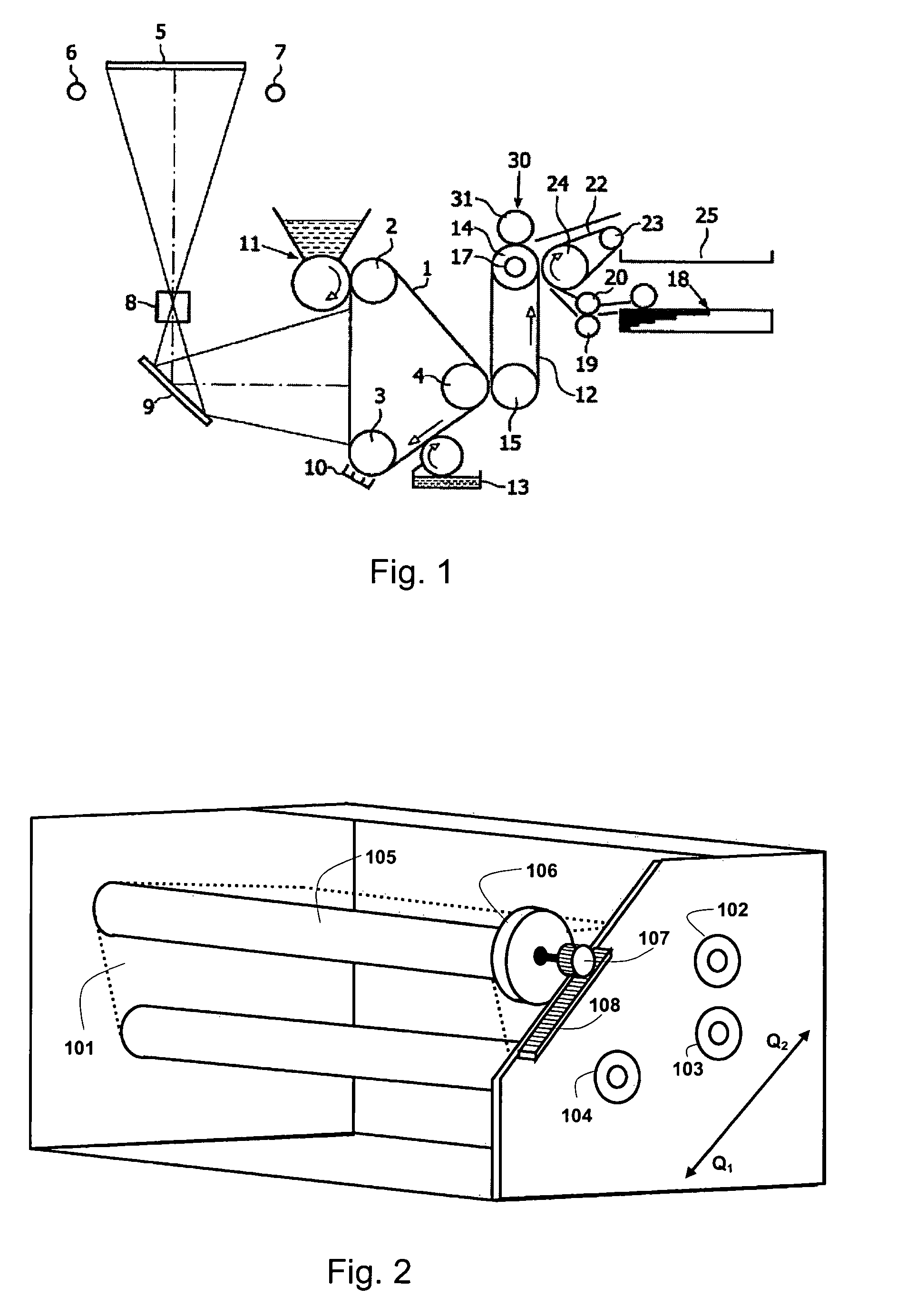
[0042]FIG. 1 diagrammatically indicates a printer in which one or more apparatus for steering a belt according to the present invention are present. The printer is provided with a unit for forming a toner image, the unit including an endless photoconductive belt 1. This belt is rotated in the indicated direction at a uniform speed using drive and guide rollers 2, 3 and 4. In the embodiment illustrated, the printer includes an analogue device in order to project onto the photoconductor 1, using flash lights 6 and 7, lens 8 and mirror 9, and an image of an original (not shown) placed on the easel 5. Prior to this imaging, the photoconductor is electrostatically charged by means of a corona unit 10. The optical imaging of the original on the charged photoconductor res...


PUM


Abstract

An apparatus for steering a belt includes a steering roller supporting the belt, a rotatable element and a transmission. The steering roller is rotatable about a first axis and pivotable about a second axis, the second axis being substantial perpendicular to the first axis. The rotatable element is rotatable about a third axis, the third axis being parallel to the first axis. The transmission is arranged for converting a rotational motion of the rotatable element about the third axis into a pivoting motion of the steering roller about the second axis. The rotatable element is rotatable by a frictional force between a side portion of the belt and the rotatable element. A method for steering a belt in a steering mechanism includes such an apparatus.

Description

CROSS-REFERENCE TO RELATED APPLICATIONS[0001]This application claims priority under 35 U.S.C. §119(a) to Application No. 07117725.7, filed in Europe on Oct. 2, 2007, the entirety of which is expressly incorporated herein by reference.BACKGROUND OF THE INVENTION[0002]1. Field of the Invention[0003]The present invention relates to an apparatus for steering a belt including a steering roller supporting the belt, a rotatable element and a transmission. The steering roller is rotatable about a first axis and pivotable about a second axis, the second axis being substantial perpendicular to the first axis. The rotatable element is rotatable about a third axis, the third axis being parallel to the first axis. The transmission is arranged for converting a rotational motion of the rotatable element about the third axis into a pivoting motion of the steering roller about the second axis. The rotatable element is rotatable by a frictional force between a side portion of the belt and the rotatab...

Claims


Application Information

Patent Timeline
Patent Type & Authority Patents(United States)
IPC IPC(8): B65G39/16
CPCG03G15/755G03G2215/00151G03G2215/00156
Inventor GRASWINCKEL, JULIUS V. C.VERSTEGEN, JAN P. J.HOLLANDS, PETER J.VAN SOEST, GERARDUS J. C.PRINSEN, KEVIN H. J. R.
Owner OCE TECH
Why Eureka
Try Eureka