Method and apparatus for attaching spindles to rails in a fence assembly

a technology of fence assembly and spindle, which is applied in the field of fencing system, can solve the problems of inability to simply place the spindle on the rail and drive a toe nail, the difference between the size of the aperture and the end of the spindle can be problematic, and the end of the spindle will not be able to be inserted into the sam

Inactive Publication Date: 2009-08-13
PLATT ROBERT E
View PDF7 Cites 23 Cited by
  • Summary
  • Abstract
  • Description
  • Claims
  • Application Information

AI Technical Summary

Benefits of technology

[0007]The device of the present invention is a racking assembly for adjustably mounting a spindle to a rail. The racking assembly includes a first member which engages the rail and a second member pivotally secured to the first member. The second member retains the spindle at an angle relative to the first member and therefore relative to the rail. As the second member pivots, the angle of the spindle relative to the rail is changed. The racking assembly gives an installer the ability to correctly set the angles of the spindles in a stair rail assembly that is to be used on stairs that range in steepness from between 25 and 40 degrees and preferably between 28 and 38 degrees.

Problems solved by technology

One of the problems encountered when building a vinyl fence assembly is that of being able to quickly and easily connect spindles between spaced apart rails.
Because of the type of material involved, the installer cannot simply place the spindle on the rail and drive a toe nail into the same.
While the method sounds easy, any differences between the size of the apertures and the ends of the spindle can be problematic.
Firstly, if the aperture is too small or is slightly incorrectly cut, the end of the spindle will not be able to be inserted into the same.
On the other hand, if the aperture is too big then the spindle will be easily inserted but will tend to move around in the aperture making the installation of the upper rail difficult.
Additionally, there will tend to be a gap around the end of the spindle and the rail thus giving the finished product an unfinished and unpolished appearance.
The problem is especially pronounced in the construction of stair rail assemblies.
Even if the spindles can be installed, they may not be angled correctly relative to the rails.

Method used


Image

  • Method and apparatus for attaching spindles to rails in a fence assembly
  • Method and apparatus for attaching spindles to rails in a fence assembly
  • Method and apparatus for attaching spindles to rails in a fence assembly

Examples


Embodiment Construction

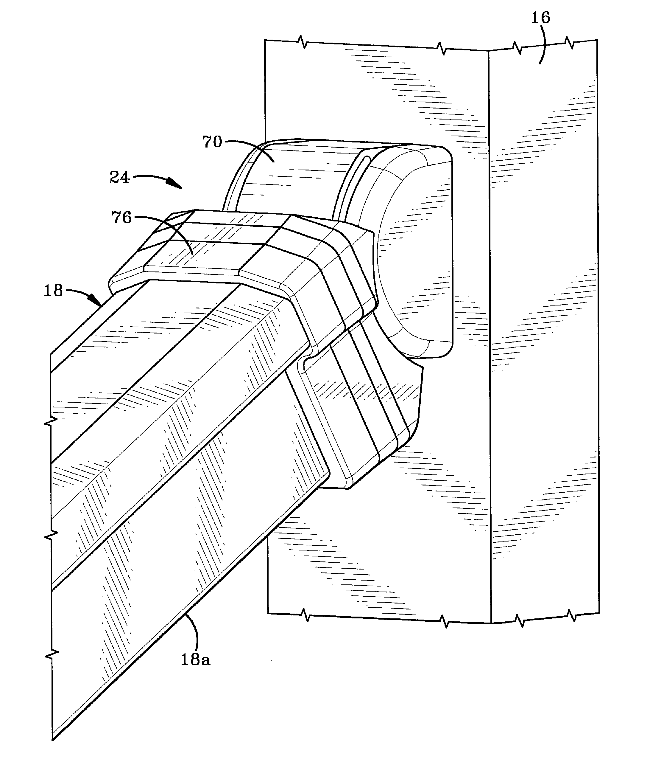
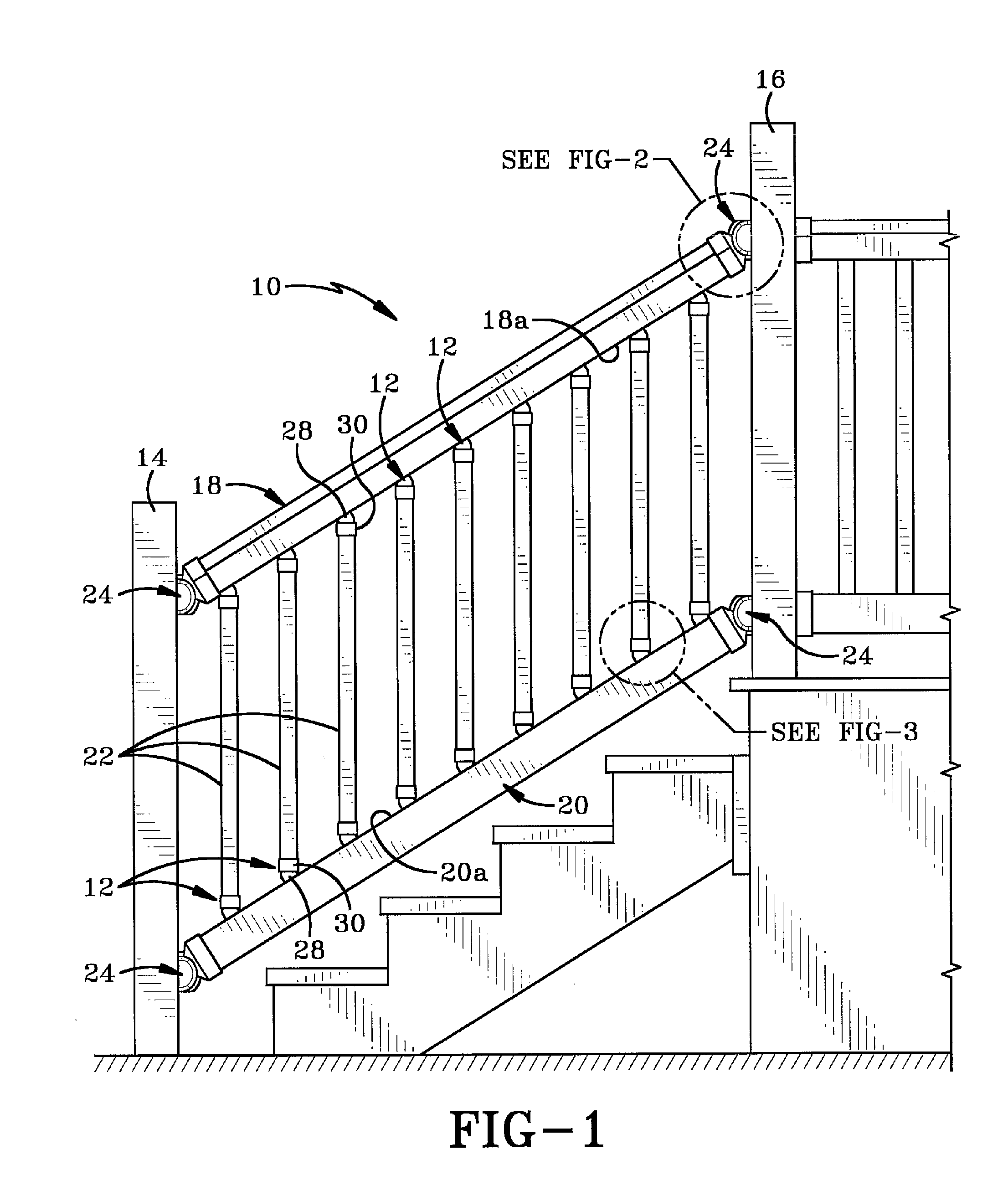
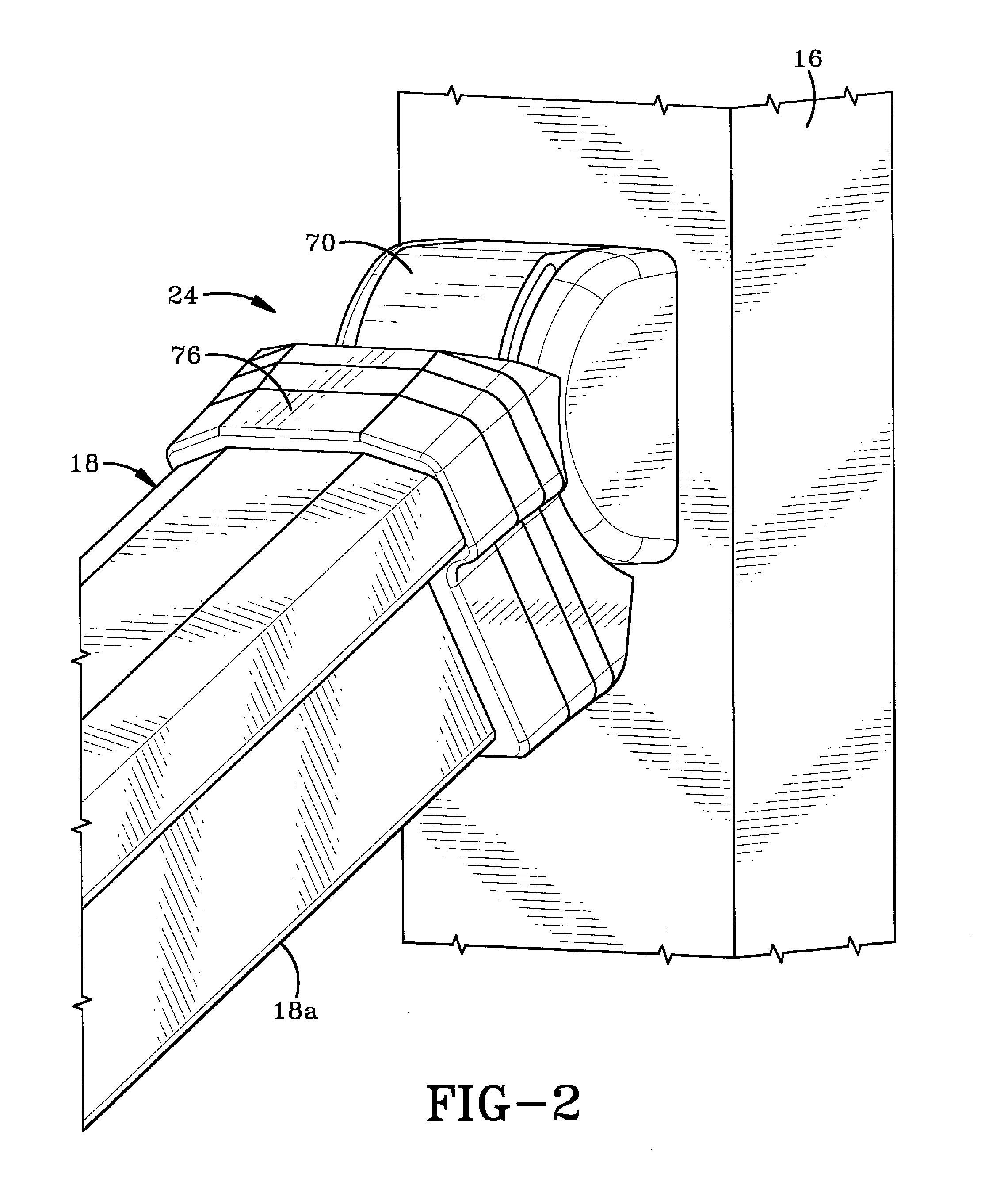
[0021]Referring to FIGS. 1-10, there is shown a stair rail assembly 10 that includes a pair of spaced-apart vertical fence posts 14, 16; a hand rail 18, a foot rail 20 and a plurality of spindles 22 extending therebetween. Each rail 18, 20 is secured to one of posts 14, 16 by way of a rail bracket assembly 24. Each rail bracket assembly 24 is adjustable so as to allow rails 18, 20 to be set at a desired angle relative to posts 14, 16. Suitable bracket assemblies 24 for this purpose are any one of the bracket assemblies disclosed in U.S. Pat. Nos. 6,698,726; 6,986,505; 7,044,451 and 7,147,212 to the present inventor, the entire disclosures of which are incorporated herein by reference. Bracket assemblies 24 enable rails 18, 20 to be set at an appropriate angle for staircases that are built at different angles of steepness. Stair rail assembly 10 further includes a plurality of spindle racking assemblies in accordance with the present invention, which assemblies are generally indicate...


PUM


Abstract

A racking assembly for adjustably mounting a spindle to a rail. The racking assembly includes a first member which engages the rail and a second member pivotally secured to the first member. The second member retains the spindle at an angle relative to the first member and therefore relative to the rail. As the second member pivots, the angle of the spindle relative to the rail is changed. In a fence rail assembly, each spindle is secured between a pair of rails by a pair of racking assemblies. Each racking assembly is mounted on one of the rails and is individually adjustable so as to set the angle of the spindle relative to the rails. The rails are secured between a pair of vertical posts. Each rail is secured to one of the posts by a bracket that is adjustable to set the angle of the rail relative to the posts.

Description

BACKGROUND OF THE INVENTION[0001]1. Technical Field[0002]This invention generally relates to fencing systems. More particularly, the invention relates to a method and apparatus for attaching spindles to a rail assembly. Specifically, the invention relates to a spindle racking assembly that includes a first member that engages the rail and a second member that engages the spindle and is pivotally mounted to the first member and movable relative thereto to set the angle of the spindle relative to the rail.[0003]2. Background Information[0004]One of the problems encountered when building a vinyl fence assembly is that of being able to quickly and easily connect spindles between spaced apart rails. Because of the type of material involved, the installer cannot simply place the spindle on the rail and drive a toe nail into the same. One of the easiest solutions is for the rail to be made with a plurality of apertures cut at predefined intervals. One end of each spindle in inserted into t...

Claims


Application Information

Patent Timeline
Patent Type & Authority Applications(United States)
IPC IPC(8): E04H17/24
CPCE04F11/1834E04F2011/1897E04H2017/1491E04H2017/1452E04H17/1421E04F2011/1827E04F2011/1819E04F2011/1821E04H17/1452E04H17/1417E04H17/1448E04H17/1488
Inventor PLATT, ROBERT E.
Owner PLATT ROBERT E
Why Eureka
Try Eureka