Angled diffuser and steam injection heater assembly

a technology of diffuser and steam injection, which is applied in the direction of lighting and heating apparatus, heating types, separation processes, etc., can solve the problems of poor steam distribution throughout the fluid to be heated, damage to equipment, including the associated piping, etc., and achieves precise angle, improved steam mixing effect, and durable end seal

Active Publication Date: 2009-08-13
PROSONIX +1
View PDF13 Cites 16 Cited by
  • Summary
  • Abstract
  • Description
  • Claims
  • Application Information

AI Technical Summary

Benefits of technology

[0007]Specifically, the configuration of the present invention provides for a diffuser that had been angled approximately 30° from vertical to facilitate better mixing of the steam with the fluid. The precise angle may be altered depending on the fluid characteristics. Also, a more durable end seal is used. The end seal in the present invention is a piston ring which prevents problems associated with the use of elastomeric rings of existing art. A more uniform diameter plug with linear travel is also an improvement over the prior art.
[0008]Other specific improvements embodied in the configuration of the present invention include the feature of an upper chamber seal that is contained outside of the diffuser and that seals two surfaces. That is, the upper chamber seal serves as a face seal to prevent flow into the diffuser through the side wall and it also prevents flow between the plug and the diffuser. Additionally, a filler material may be provided to prevent infiltration of fluid or solids into the steam chamber. The filler material is optionally added to the space between the plug and diffuser to prevent slurry solids from migrating into the space during down time. Finally, variable diffuser hole diameters are used to maintain adequate max flux of steam to penetrate viscous fluids, it being known that different fluid viscosities require differing steam jet characteristics in order to penetrate and condense in the flowing liquid.

Problems solved by technology

As a result, there can be poor steam distribution throughout the fluid to be heated and subsequently “hot pockets” inside the pipe.
In a highly viscous fluid, these hot pockets can lead to instability and “steam hammer.” This can also lead to damaging of the equipment, including the associated piping.
In the experience of this inventor, such seals can quickly wear out as they ride over the holes that are contained within the diffuser.
This occurs because the seals can “extrude” into and be damaged by the diffuser holes as the seals are repeatedly moved across the holes.
In the experience of this inventor, such windows can lead to deformation in the plug when under pressure.
Such deformation causes non-uniform gaps between the plug and the diffuser together with uneven and premature wear.
It also causes premature plug failure.

Method used


Image

  • Angled diffuser and steam injection heater assembly
  • Angled diffuser and steam injection heater assembly
  • Angled diffuser and steam injection heater assembly

Examples


Embodiment Construction

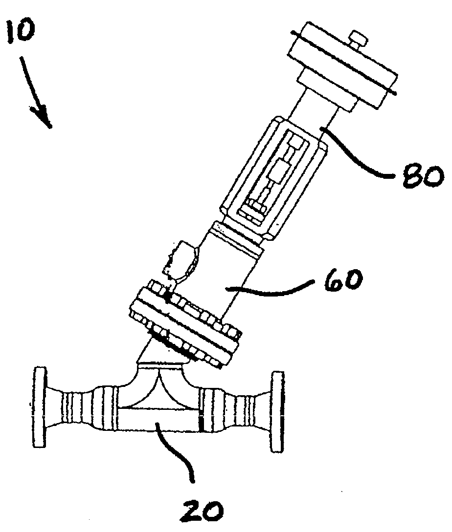
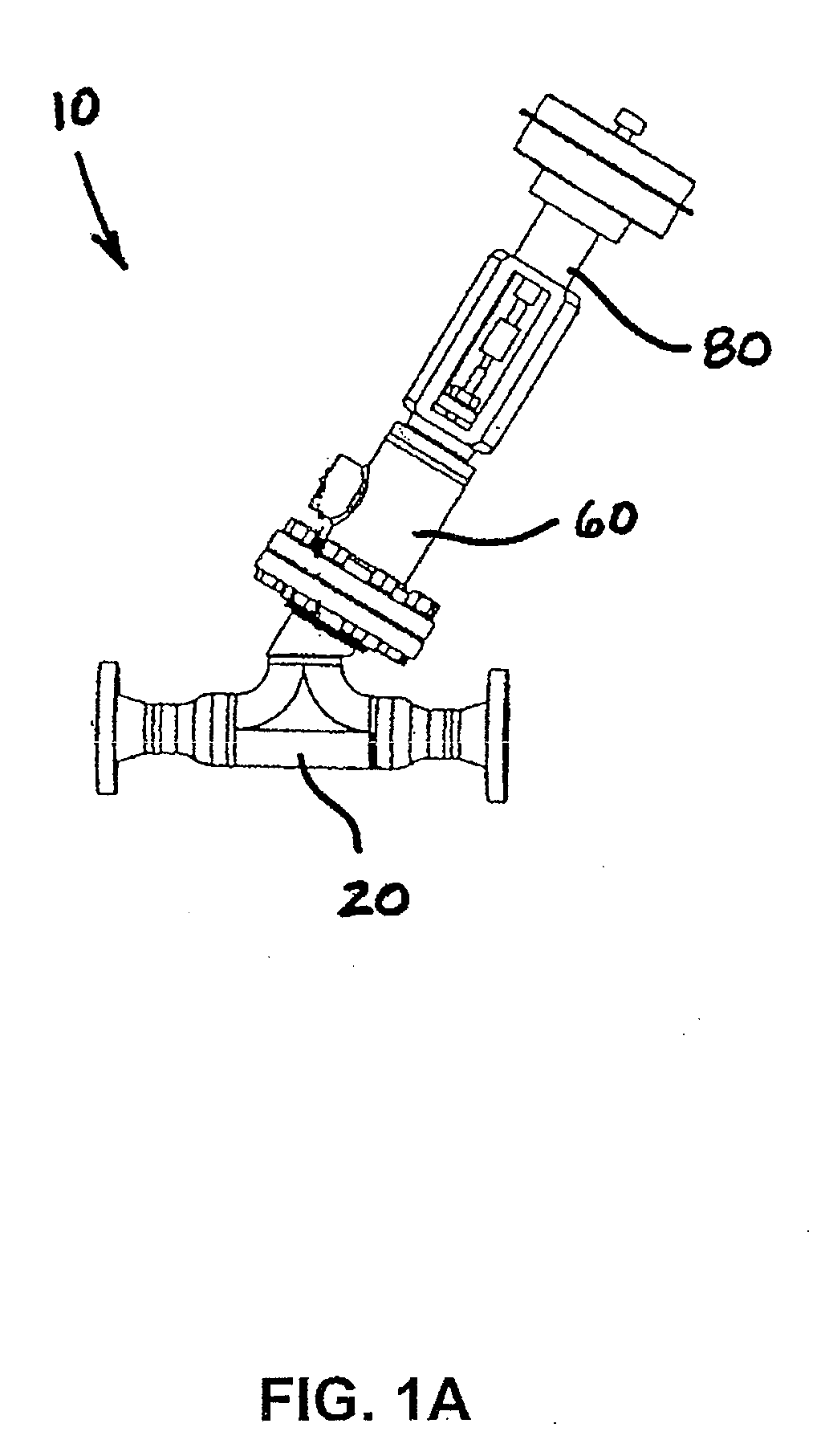
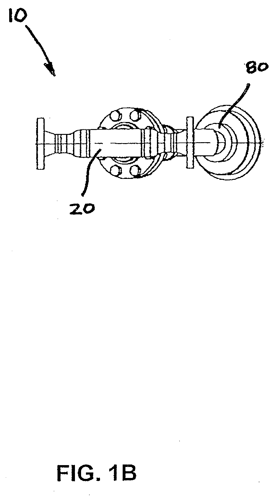
[0017]Referring now to the drawings in detail, wherein like numbered elements correspond to like elements throughout, FIGS. 1A through 1C show the angled diffuser and assembly, generally identified 10, constructed in accordance with the present invention. As shown in FIG. 1A, it will be seen that the assembly 10 comprises several component parts. The primary parts are the liquid chamber 20, the diffuser 40, the steam chamber 60 and the actuator 80.

[0018]The liquid chamber 20 includes a fluid inlet 22 and a fluid and steam outlet 24. The liquid chamber 20 also includes an aperture 26 to which is mounted the diffuser 40. The diffuser 40 includes a diffuser body 42 having a proximal end 41 and a distal end 43. Movable within the diffuser body 42 is a modulating plug 46. The modulating plug 46 has a proximal end 45 and a distal end 47. It is to be understood that the modulating plug 46 of the preferred embodiment is configured to be of a uniform diameter and to travel linearly within th...


PUM

PropertyMeasurementUnit
angleaaaaaaaaaa
angleaaaaaaaaaa
angleaaaaaaaaaa

Abstract

An improved configuration for an in-line direct contact diffuser-type steam injection heater provides for a diffuser whereby steam flow is controlled using an angled sonic diffuser and plug arrangement. The steam flow is controlled by means of a steam plug which selectively exposes holes through which the steam passes. In the preferred embodiment, the configuration provides for a diffuser that had been angled approximately 30° from vertical to facilitate better mixing of the steam with the fluid. The precise angle may be altered depending on the fluid characteristics. A more durable end seal is also used. The end seal is a piston ring which prevents problems associated with the use of elastomeric rings of existing art. A more uniform diameter plug with linear travel is also an improvement over the prior art.

Description

[0001]This application claims the benefit and priority of U.S. Provisional Patent Application No. 61 / 023,132 filed Jan. 24, 2008.FIELD OF THE INVENTION[0002]The present invention relates generally to direct contact steam injection heaters that are used for heating certain types of slurries. More specifically, it relates to an angled diffuser that is used within a diffuser-type steam injection heater assembly.BACKGROUND OF THE INVENTION[0003]In direct contact steam injection heaters, steam is directly mixed into a flowing fluid (e.g. liquid or slurry) that is in the process of being heated. Direct contact steam injection heaters are well known in the art and are very effective at transferring heat energy to the flowing fluid. They provide rapid heat transfer with virtually no heat loss to the atmosphere, and also transfer both the latent and the available sensible heat of the steam to the liquid slurry.[0004]Diffuser-type steam injection heaters are also known in the art. In the expe...

Claims


Application Information

Patent Timeline
Patent Type & Authority Applications(United States)
IPC IPC(8): B01F5/04B01F3/04
CPCF28C3/08Y10S261/10Y10S261/76
Inventor CINCOTTA, BRUCE A.
Owner PROSONIX
Why Eureka
Try Eureka