Valve end cover drilling device

A technology of punching device and end cap, which is used in feeding device, boring/drilling, drilling/drilling equipment, etc. problems of uniformity

Active Publication Date: 2018-09-11
重庆博创知识产权运营有限公司
View PDF13 Cites 12 Cited by
  • Summary
  • Abstract
  • Description
  • Claims
  • Application Information

AI Technical Summary

Problems solved by technology

Since the valve end cover is manually rotated, the rotation angle of the valve end cover has a certain error, which makes the distribution o

Method used


Image

  • Valve end cover drilling device
  • Valve end cover drilling device

Examples


Example Embodiment

[0014] The following is a further detailed description through specific implementations:

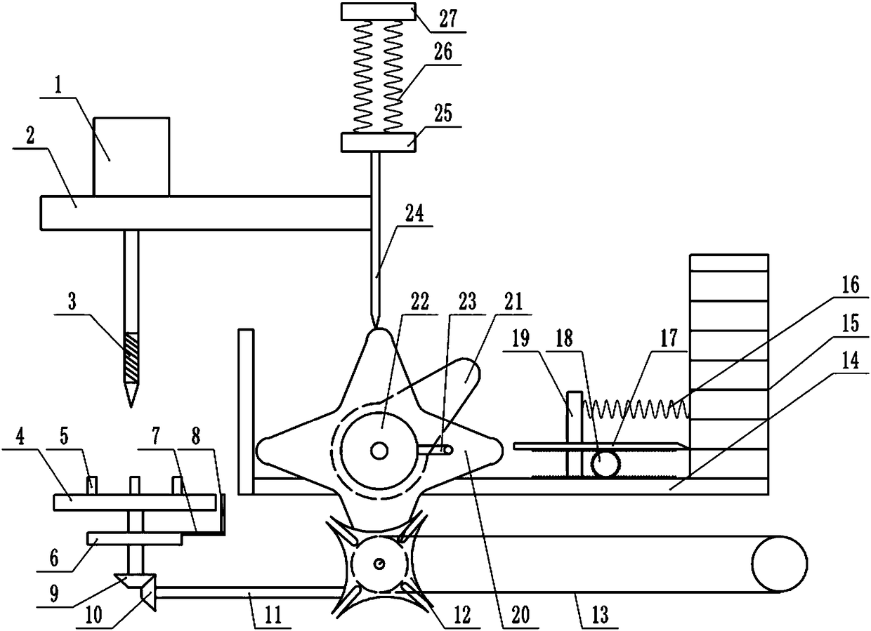
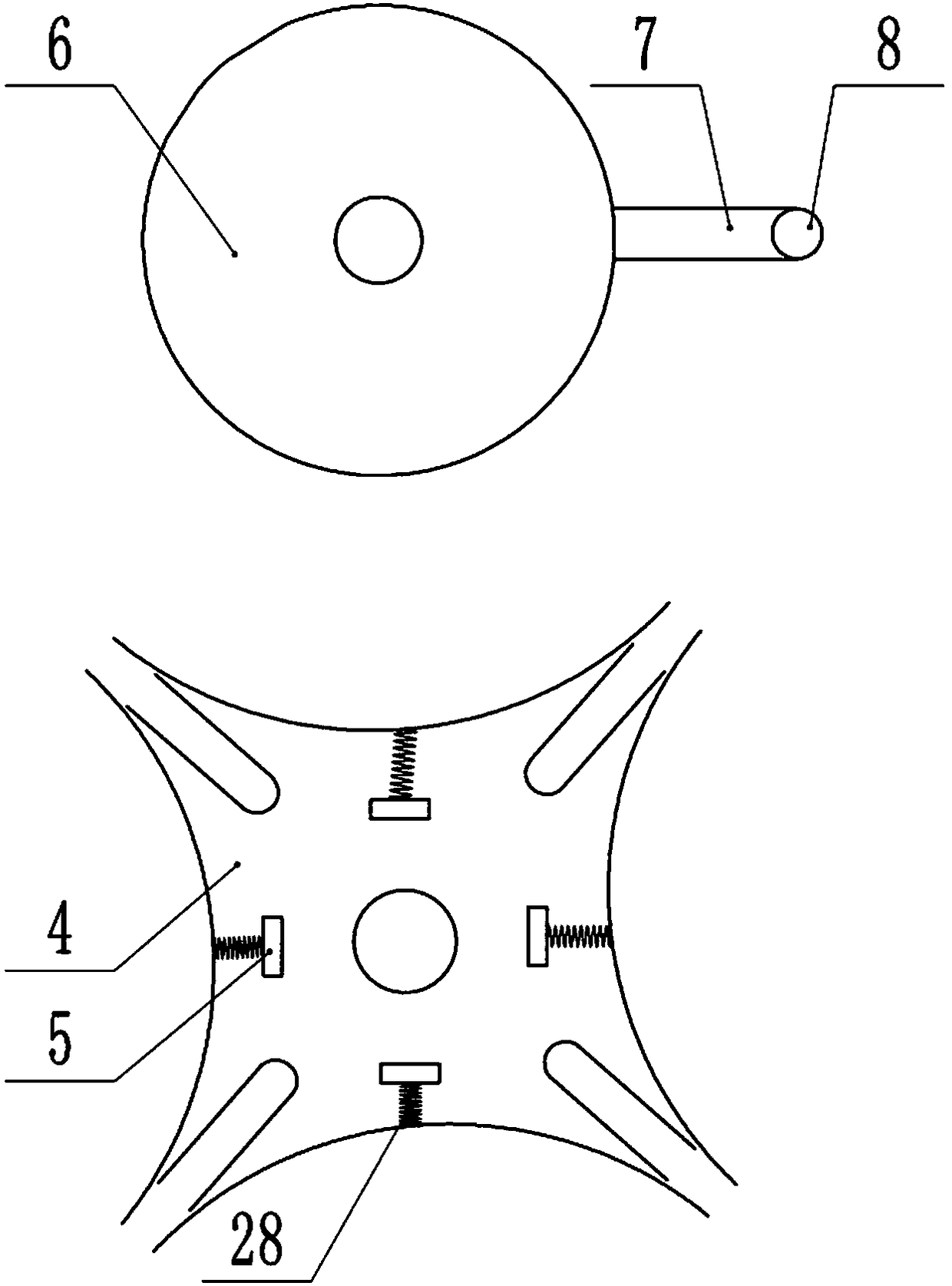
[0015] The reference signs in the drawings of the specification include: drilling motor 1, cross plate 2, drill bit 3, first sheave 4, splint 5, first turntable 6, first drive rod 7, first pin 8, first Bevel gear 9, second bevel gear 10, connecting shaft 11, second sheave 12, conveyor belt 13, baffle plate 14, blanking box 15, spring 16, partition plate 17, gear 18, first vertical plate 19, rotation The disc 20, the cam 21, the second rotating disc 22, the second driving rod 23, the driven rod 24, the connecting block 25, the compression spring 26, the fixed block 27, and the clamping spring 28.

[0016] The embodiment is basically as attached Figure 1-Figure 2 Shown: a valve end cover punching device, including a frame and a drilling motor 1. A vertically downward drill bit 3 is installed on the drilling motor 1, and a vertical driven rod 24 is slidingly connected to the frame A fixed blo...


PUM


Abstract

The invention relates to a valve end cover drilling device. The valve end cover drilling device comprises a machine frame and a drilling motor; a vertically-downward drill bit is installed on the drilling motor; a vertically-arranged driven rod is slidably connected to the machine frame, a compressed spring is arranged between one end of the driven rod and the machine frame, the driven rod is fixedly connected with a transverse plate, the drilling motor is installed on the transverse plate, and the machine frame is provided with a reciprocating mechanism which is used for enabling the driven rod to move in a reciprocating mode; a first groove wheel rotationally connected to the machine frame is arranged under the drill bit and provided with a fixture used for clamping a valve end cover; the machine frame is rotationally connected with a first rotary disc, the first rotary disc is fixedly connected with a first driving rod, and a first pin shaft capable of being inserted into a radial groove formed in the first groove wheel is fixedly connected to the first driving rod; a linkage mechanism is connected between the reciprocating mechanism and the first rotary disc; and the reciprocating mechanism is connected with a driving mechanism enabling the reciprocating mechanism to work. Through the scheme, automation rotating of the valve end cover is achieved, and the drill bit drills aplurality of uniformly-distributed threaded holes in the valve end cover.

Description

technical field [0001] The invention relates to the field of valve processing, in particular to a valve end cover punching device. Background technique [0002] The valve is a control component in the fluid delivery system, which has functions such as cut-off, adjustment, flow diversion, reverse flow prevention, pressure stabilization, flow diversion or overflow pressure relief. The valve is mainly composed of three parts: the valve body, the opening and closing member and the end cover. Among them, the end cover of the valve is mostly disc-shaped, and the valve end cover is provided with a number of radially evenly distributed threaded holes centered on the center of the valve end cover. , similar to a flange, which facilitates fixing the valve end cover to the valve body by bolts. During the processing of the valve end cover, a drill bit is required to drill several threaded holes on the valve end cover. In the prior art, the valve end cover needs to be manually rotated s...

Claims


Application Information

Patent Timeline
IPC IPC(8): B23B41/00B23Q5/22B23Q1/25
CPCB23B41/00B23Q1/25B23Q5/22
Inventor 罗贵良
Owner 重庆博创知识产权运营有限公司
Why Eureka
Try Eureka