

Assembled camshaft
A camshaft, combined technology, used in valve details, engine components, machines/engines, etc., can solve problems such as inconvenient oil supply adjustment
Inactive Publication Date: 2011-06-22
运城常运动力机械有限公司
View PDF0 Cites 15 Cited by
- Summary
- Abstract
- Description
- Claims
- Application Information
AI Technical Summary
Problems solved by technology
[0003] In order to solve the problem of inconvenient adjustment of oil supply advance angle, the present invention proposes a combined camshaft
Method used
View moreImage
Smart ImageViewing Examples

Examples
Embodiment Construction
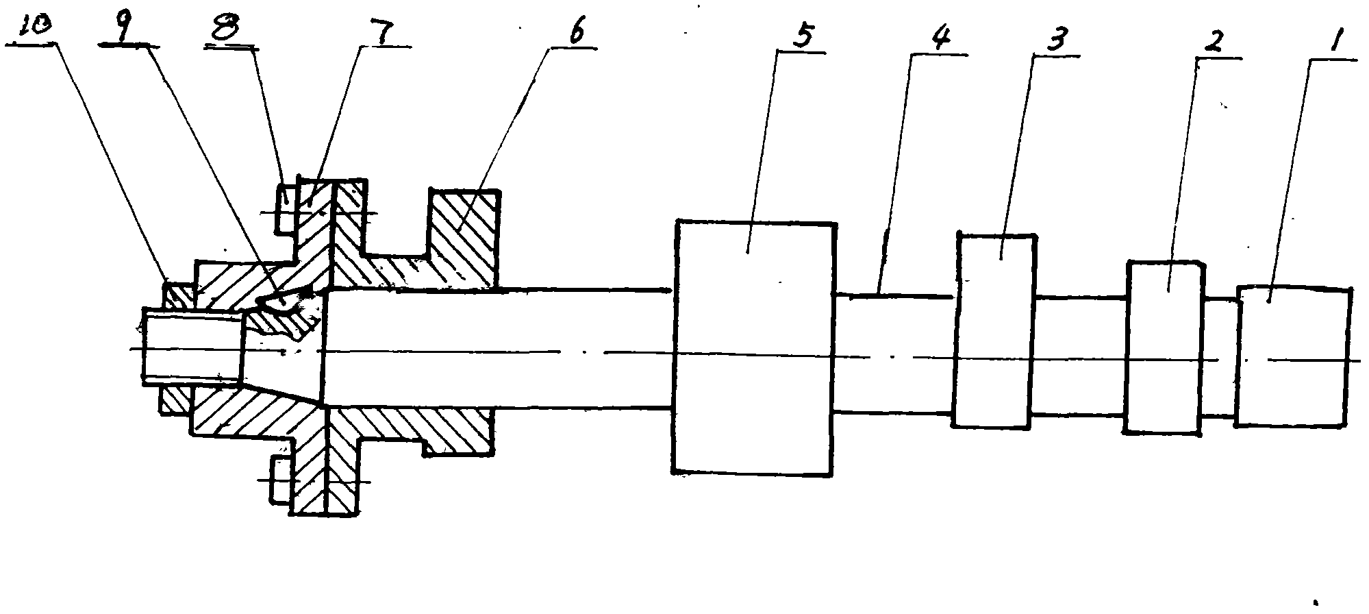
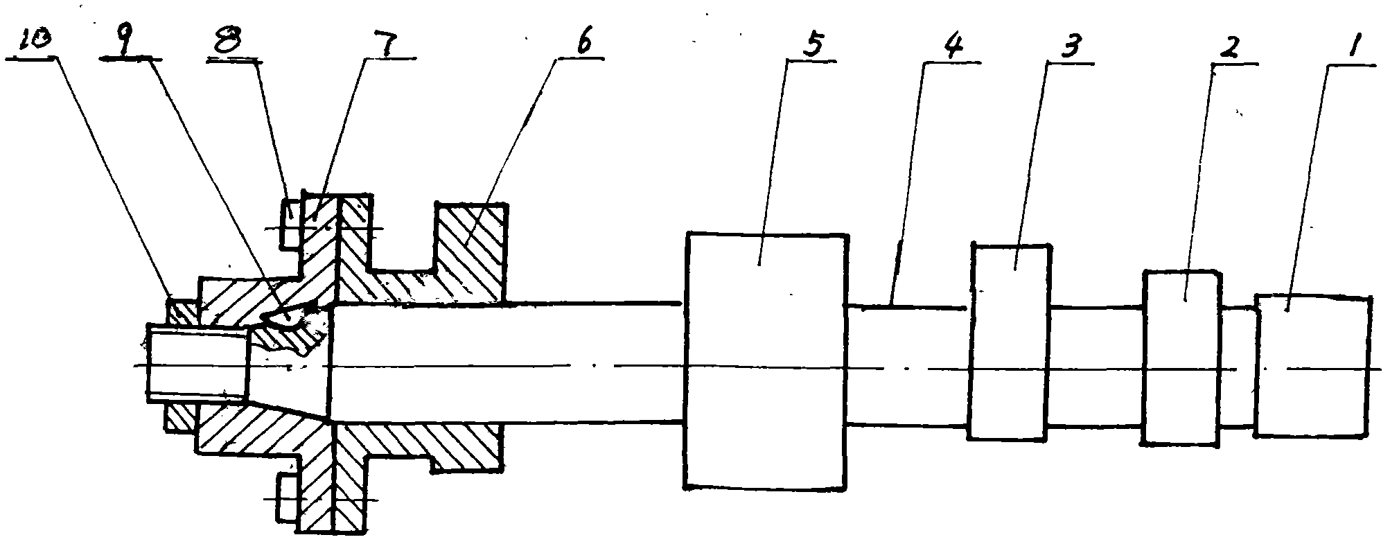
[0006] As shown in the accompanying drawings, the camshaft 4 of the present invention is made with intake cam 3, exhaust cam 2, support journals 1 and 5, the oil supply cam 6 of the fuel injection pump is slipped on the camshaft 4, and the drive disc 7 passes through The key 9 is fastened on the camshaft 4 with a nut 10, and the fuel supply cam 6 of the fuel injection pump is connected with the drive plate 7 through a screw 8.
[0007] When adjusting the advance angle of fuel supply, loosen the screw 8, move the oil supply cam 6 of the fuel injection pump to make it rotate an angle relative to the drive plate 7, and then tighten the screw 8 to complete the adjustment of the advance angle of fuel supply.
Login to View More PUM
 Abstract
The invention discloses an assembled camshaft for a single cylinder diesel. A central hole of an oil supply cam of a fuel injection pump of the assembled camshaft is slidably sleeved on the camshaft and is connected with a driving disk; and the driving disk is fastened on the camshaft through a key and a nut. The defects that in the cam of the fuel injection pump of the single cylinder diesel, an oil injection angle cannot be adjusted randomly, necessary conditions are provided for arranging an oil supply angular advance automatic adjustment device on the single cylinder diesel, and the invention has the characteristics that the assembled camshaft is easy to implement, has reliable performance, can be operated quickly and the like.
Description
technical field [0001] The combined camshaft of the invention relates to the technical field of internal combustion engines, in particular to the technical field of single-cylinder diesel engines. Background technique [0002] The structure of the camshaft of present known single-cylinder diesel engine is: the fuel supply cam of the fuel injection pump and the gas distribution cam are made on the same shaft, and the fuel supply cam of the fuel injection pump cannot adjust the angle arbitrarily. The adjustment of the fuel supply advance angle needs to remove the fuel injection pump and increase or decrease the gasket of the fuel injection pump to adjust, the actual operation is very inconvenient. More importantly, the camshaft of this structure cannot be equipped with an automatic adjustment device for the oil supply advance angle. Contents of the invention [0003] In order to solve the problem of inconvenient adjustment of the oil supply advance angle, the present invent...
Claims
Login to View More Application Information
Patent Timeline
 Patent Type & AuthorityApplications(China)
IPC IPC(8): F01L1/047F01L1/06
Inventor傅大千
Owner运城常运动力机械有限公司