
Route guidance system

a route guidance and route technology, applied in road vehicle traffic control, instruments, computing, etc., can solve the problems of many route guidance points that cannot be displayed, color images require a long transfer time, and cannot be solved, so as to achieve the effect of more efficient calculation

Inactive Publication Date: 2009-08-13
PANASONIC CORP
View PDF0 Cites 28 Cited by
  • Summary
  • Abstract
  • Description
  • Claims
  • Application Information

AI Technical Summary

Benefits of technology

[0047]Accordingly, the visible region can be calculated more efficiently than a conventional plane operation method, and the route guidance processing thus can be efficiently performed.

Problems solved by technology

However, the following problems have not been solved in the prior art.
(1) In the prior art, a movement instruction at an intersection such as ‘Turn right at the intersection of . . . ’ is shown based on route data. But, in the premises in the case of diagonally crossing an open space such as an atrium, a vault and a concourse although giving route guidance based on landmarks is more simple, the prior art gives a guidance so as to go around the sides of the open space, for example, along the route data on the map;
(2) In the route guidance using the portable terminal of a low resolution and a small screen, a color image is hard to watch when it is directly sent to the terminal. In addition, the color image requires a long transfer time due to a large data quantity. Further, in an image of low compress ion effect even by a binary image, many route guidance points cannot be displayed when the route becomes long;
(3) In the case of guiding a route with a map divided in frames, there are individual variations as to where to display the route to be more understandable, some users feel that the route is hard to read if it is always displayed in the center because of lack of continuity between frames and other users feel it is better to display the route always in the center, therefore, display must be changed for each user;
(4) In the case of performing route leading, since current positional information of the user from position detection means includes an error, the current position goes off from a position where the user actually is when the current position is guided based on the positional information from the position detection means. Further, when a traveling direction of the route is guided based on the positional information from the position detection means, it is different from the actual traveling direction of the user; and
(5) In the case of performing position detection using the tag, there is a case where a reader cannot detect the tag, and thus appropriate route leading cannot be made.
However, in Japanese Patent Laid-Open No. 9-1672 97, whether or not a straight line from the current posit ion to the intersection crosses a polygon, which constitutes landmarks near the intersection is only deter mined, and since this is not a processing to determine what is in the range of vision, it is impossible to extract the landmark in the range of vision and guide the route utilizing the landmark.
However, in the method by the plane scanning method in which the half line from the viewpoint is made rotate once, although n log n is certainly enough for the processing of (3), S0 needs to be obtained after an optimal line segment 1 is decided in the processing of (1), and there has existed a problem that a calculation amount in deciding the half line l was large and it was not necessarily performed by a small task considering the processing of (1).

Method used


Image

  • Route guidance system
  • Route guidance system
  • Route guidance system

Examples


embodiment 1

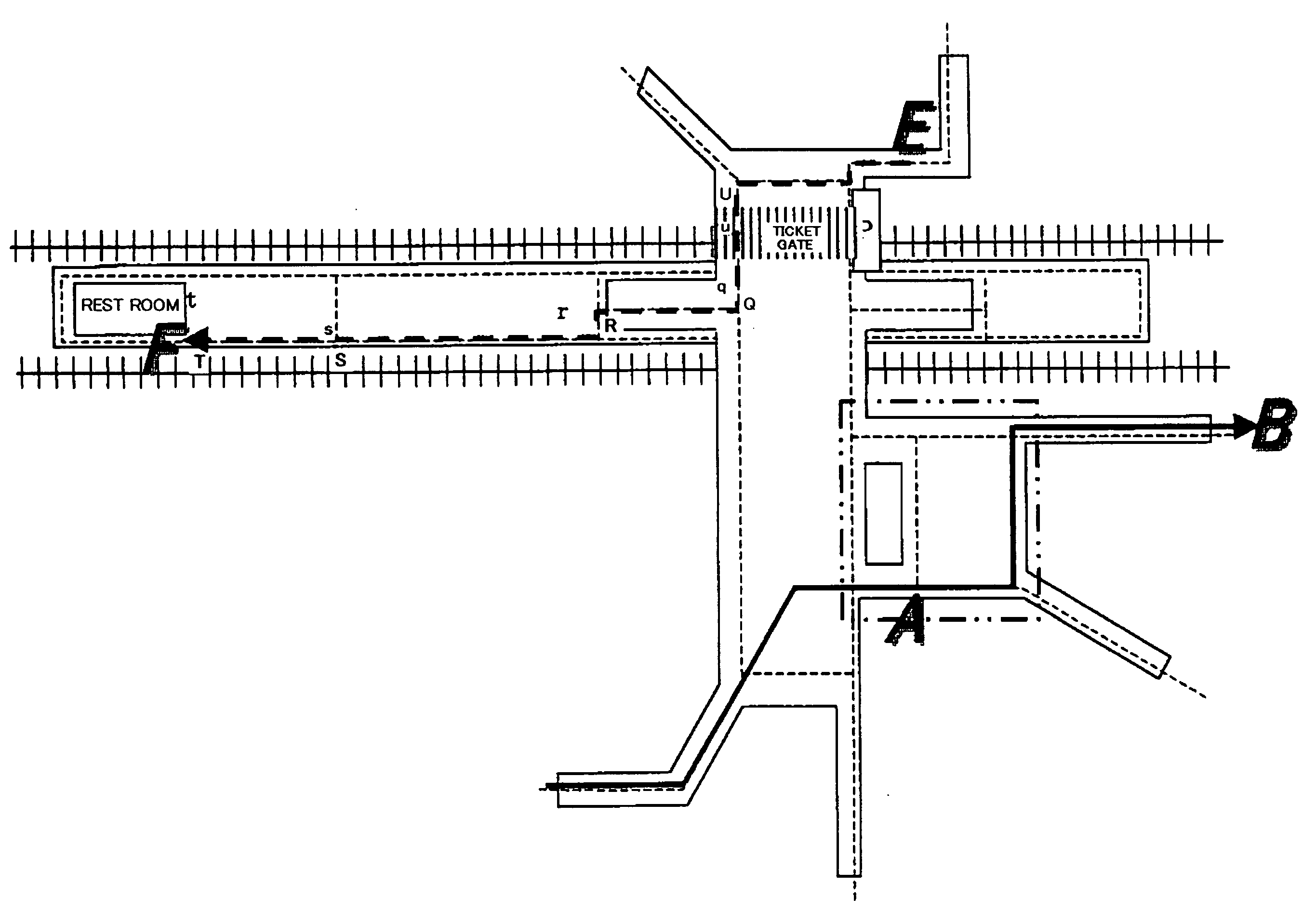
[0154]The route guidance means 1 will be described based on an example. Herein, consideration will be given to the case of passing in the premises from A to B as shown by the solid line arrow. The route data is drawn in the premises in dotted lines on the map DB40. The user loses his / her way at point A, and rang a system using the portable terminal 30 first. The user enters a destination B through the user interface of the portable terminal 30. A portable terminal Pa reads an ID in Ta from the posit ion detection Ta, and transmits data: a tag ID; the terminal being a PDA type terminal; and the destination being B to the route guidance apparatus 10.

[0155]The processing will be described along the flowchart of the route guidance means 1 shown in FIG. 5.

[0156]In the route guidance means 1, the position determination means 11 outputs a user's position A(15,23) in the premises (step 51), the route search means 141 set the current position A as a variable (Entrance) (step 52), and perform...

embodiment 2

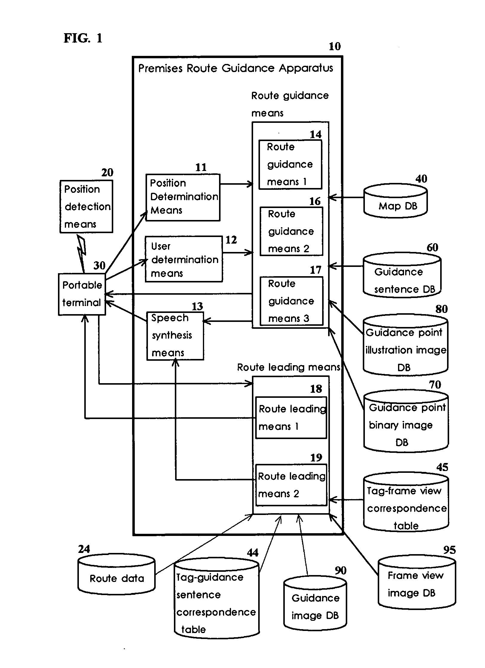
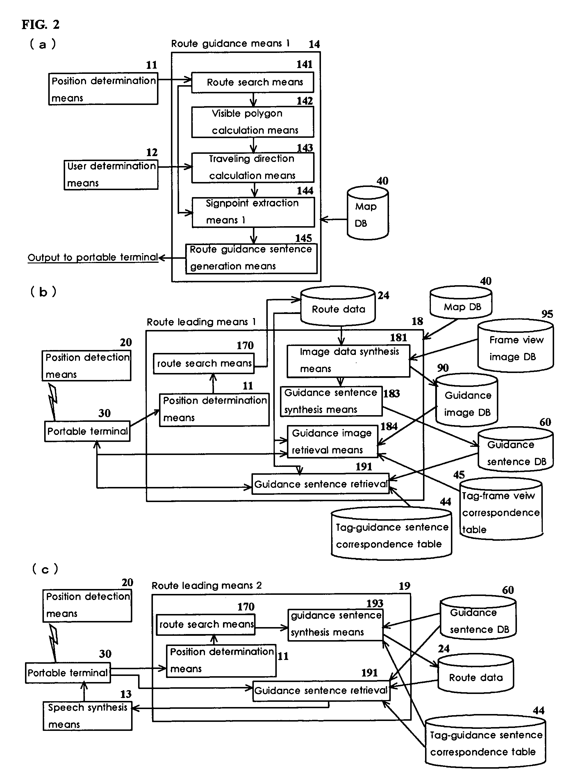
[0158]FIG. 8 is the block diagram showing the configuration example of the route guidance means 2 in the present invention, and it comprises: the map DB40 where the route data for searching the route in the premises; the route search means 170 that searches the route in the premises; the guidance point illustration image DB70 where the illustration images of the guidance points are accumulated; the guidance point binary image DB80 where the binary images of the guidance points are accumulated; image data retrieval means 171 that retrieves the image of the guidance point based on a route search result; the guidance sentence DB60 where the guidance sentences are accumulated; guidance sentence generation means 173 that generates the guidance sentence from the guidance sentence DB based on the route search result; visible polygon calculation means 174 as an example of the visible region calculation means that calculates a range that can be seen from the current position; traveling direc...

embodiment 3

[0162]FIG. 16 is the block diagram showing a configuration example of the route guidance means 2 in the present invention, and it comprises: the map DB40 where the route data for searching the route in the premises is accumulated; route search means 161 that searches the route in the premises; frame map generation means 1 that matches connection points of the route in each frame map to generate the frame map; the guidance sentence DB60 where the guidance sentences are accumulated; and guidance sentence generation means 163 that gene rates the guidance sentence from the guidance sentence DB based on the route search result.

[0163]The processing of the embodiment of the route guidance means 2 will be described along the flowchart of the route guidance means 2 shown in FIG. 17 and the flowchart of the frame map generation means 162 shown in FIG. 18. Herein, consideration will be given to the case of passing in the premises from E to F as shown by the broken line arrow. In the route guid...


PUM


Abstract

Provided is a route guidance system that provides a route in premises in order to perform service of route guidance in the premises, which includes: a route guidance apparatus, which is comprised of visible region calculation means that calculates a range where a user can see, signpost extraction means that extracts a signpost to be guided from a visible region, route search means that searches the route from a starting point to a destination, route information generation means that comprises guidance map generation means that generates a map for guidance and guidance sentence generation means that generates the guidance sentence, route leading means that obtains current positional information to send appropriate guidance information to a portable terminal, and position determination means that performs coordinate conversion to information from a position detection apparatus of the user; a portable terminal apparatus including a user interface, which displays an image or a route guidance sentence; a position detection apparatus that obtains current positional information of the user; a map DB that stores data / signpost information regarding the route; a guidance sentence DB that stores basic data for generating the guidance sentence; and route information data that stores guidance data output from the route information generation means.

Description

BACKGROUND OF THE INVENTION[0001]1. Field of the Invention[0002]The present invention relates to an apparatus and a system for providing a person, who is not good at reading a map, with guidance including landmark information and route information regarding a direction where the moving person needs to proceed when moving in an architectural structure such as a building with a method using an image or the like such that the user does not became lost in an open space. Further, the present invention also relates to a calculation apparatus of a visible region and a program thereof, which are necessary in extracting a land mark to support the movement of the moving person.[0003]2. Description of the Prior Art[0004]In the prior art, there has existed the following known references regarding a system that performs route guidance in premises or in a building.[0005]The invention disclosed in Japanese Patent Laid-open No. 8-190688 is one that provides a pedestrian in the premises, who is a pe...

Claims


Application Information

Patent Timeline
IPC IPC(8): G08G1/095G06K9/00G01C21/20
CPCG01C21/20
Inventor SHIMADA, TAKANORIFURUKAWA, YOSHIYUKI
Owner PANASONIC CORP
Learn More