Tapered roller bearing with displaceable rib

a technology of displaceable ribs and roller bearings, which is applied in the direction of bearings, shafts and bearings, bearings, etc., can solve the problems of cones tending, difficult maintenance, and line-to-line contact, often referred to as zero-end play

Inactive Publication Date: 2009-08-13
THE TIMKEN CO
View PDF5 Cites 14 Cited by
  • Summary
  • Abstract
  • Description
  • Claims
  • Application Information

AI Technical Summary

Problems solved by technology

Another condition of line-to-line contact, often referred to as zero end play, is difficult to maintain.
A light preload is preferred, but too much preload can damage the bearings.
On the other hand, the radial expansion of the cones tends to increase the preload.
While a slight preload is desirable for a pair of single row tapered roller bearings mounted on opposition, too much preload is detrimental.
Differential thermal expansion between the cones and cups and the shaft and housing to which they are respectively fitted can produce excessive preload.
That preload may:reduce bearing lifeincrease bearing noise and vibrationincrease bearing generated heatincrease bearing torqueincrease damage to bearing lubricantincrease roller contact stressincrease cage damage

Method used


Image

  • Tapered roller bearing with displaceable rib
  • Tapered roller bearing with displaceable rib
  • Tapered roller bearing with displaceable rib

Examples


Embodiment Construction

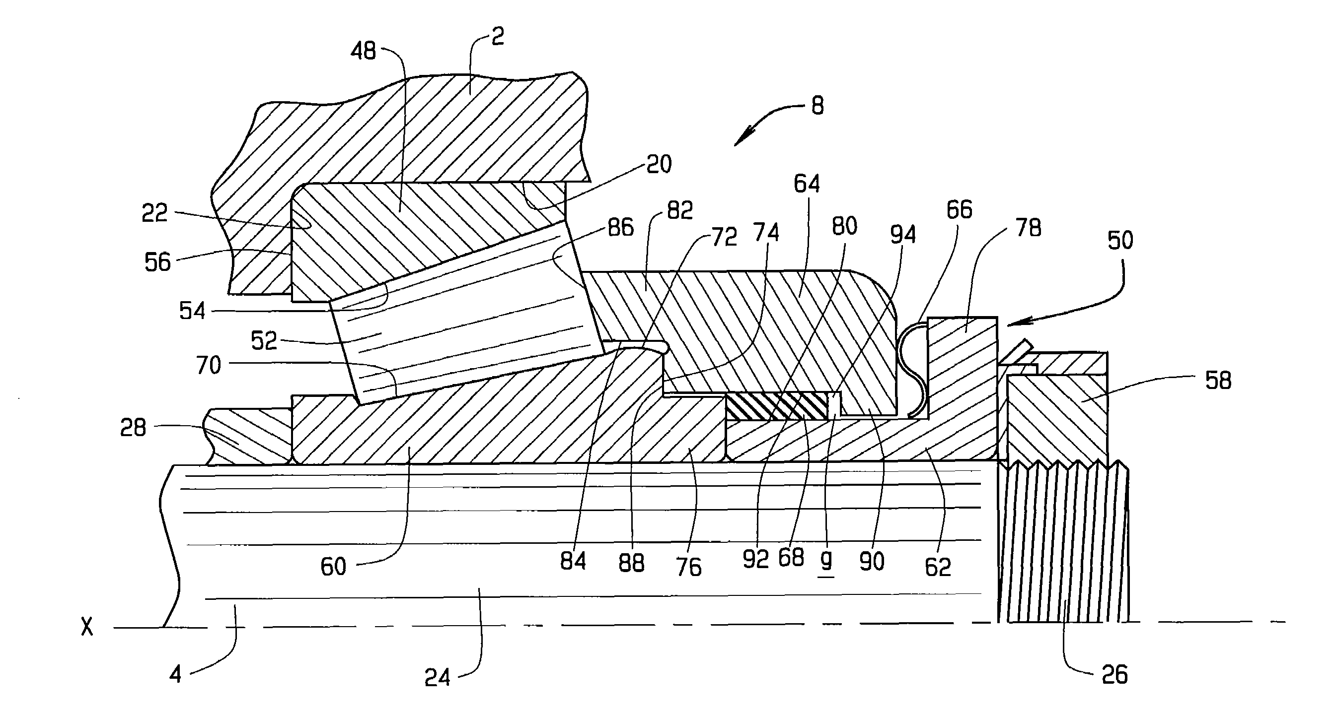
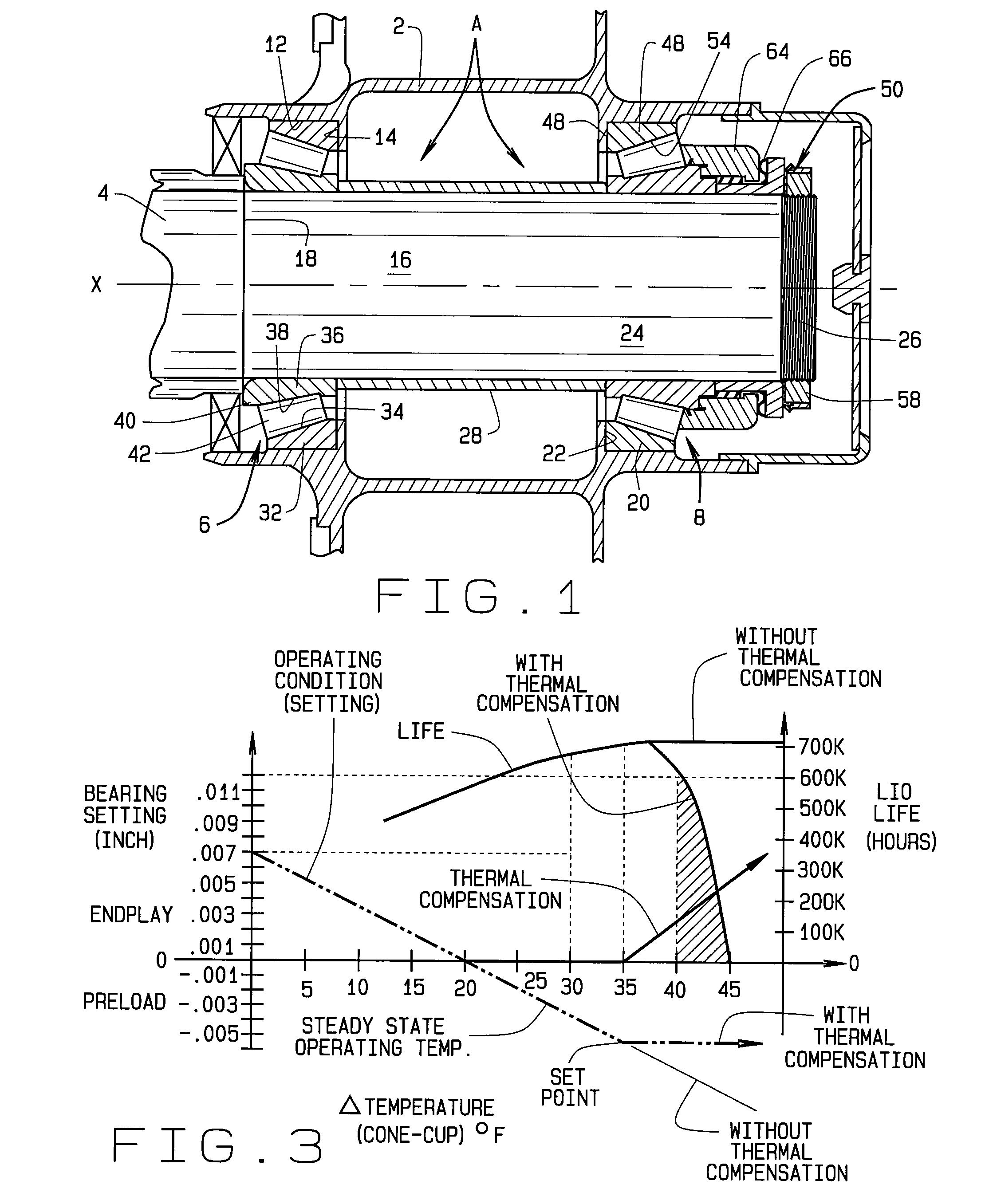
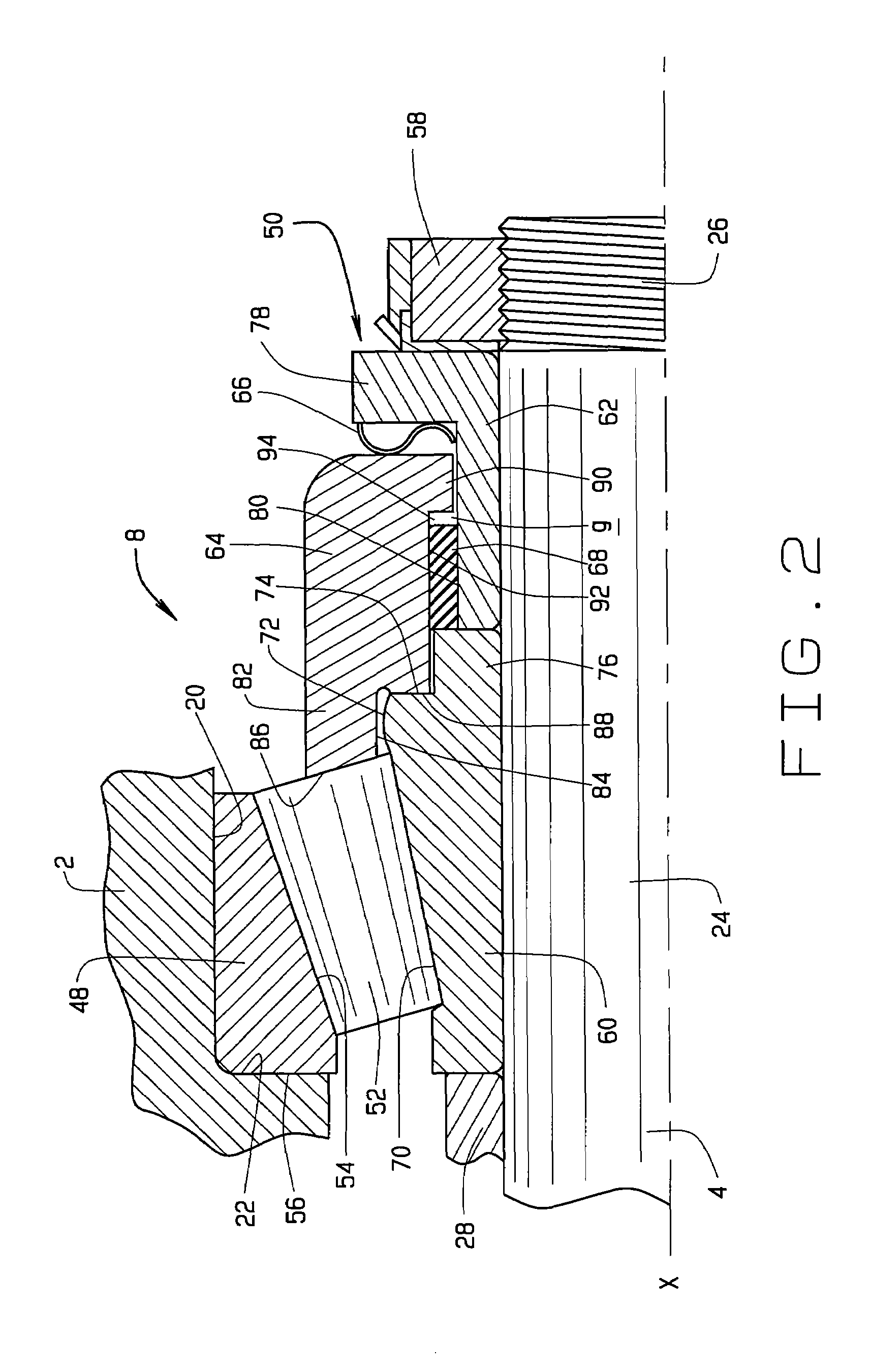
[0025]Referring now to the drawings, a bearing system A (FIG. 1) exists between a housing 2 and a shaft 4 to enable one to rotate relative to the other about an axis X. For example, the housing 2 may remain fixed and the shaft 4 may rotate in it. On the other hand, the shaft 4 may take the form of a fixed spindle about which the housing 2 rotates, in which event the housing 2 may be a hub. The bearing system A includes two antifriction bearings-namely a single row tapered roller bearing 6 of conventional design and another single row tapered roller bearing 8 configured to compensate for differential thermal expansion between housing 2 and shaft 4 as well as between components of the bearings 6 and 8 themselves, a compensating bearing so to speak. The two bearings 6 and 8 are mounted in opposition to transfer radial loads between the housing 2 and shaft 4 and axial (thrust) loads in both axial directions as well. The system A as illustrated has the bearings 6 and 8 mounted in the ind...


PUM

PropertyMeasurementUnit
angleaaaaaaaaaa
forceaaaaaaaaaa
temperatureaaaaaaaaaa

Abstract

A bearing system (A) that supports a shaft (4) in a housing (2) includes two single row tapered roller bearings (6, 8) mounted in opposition. One of the bearings (8) compensates for thermal variations that would otherwise produce excessive preload in the system. It has a conventional cup (48) in the housing and tapered rollers (52) arranged in a single row along the raceway (54) of the cup. It also has a compensating assembly (50, 100, 110, 120, 130) on the shaft, and it includes a ribless cone (60) having a raceway (70) around which the rollers are organized, an axially displaceable rib ring (64) for positioning the rollers, a spring (66) for urging the rib ring against a stop surface (74) on the cone, and a compensating ring (68) formed from a material having a high coefficient of thermal expansion for displacing the rib ring against the force exerted by the spring when the temperature of the compensating assembly exceeds a prescribed set point temperature so as to reduce preload in the bearing system.

Description

CROSS-REFERENCE TO RELATED APPLICATIONS[0001]This application derives and claims priority from U.S. Provisional Application 60 / 817,708, filed Jun. 30, 2006, which is incorporated herein by reference.TECHNICAL FIELD[0002]This invention relates in general to tapered roller bearings and more particularly to tapered roller bearings having displaceable ribs that compensate for thermal differentials and to a method of controlling the setting in bearings.BACKGROUND ART[0003]A tapered roller bearing in its simplest form has a cup (outer race) that is typically fitted to a housing, a cone (inner race) that is typically fitted over a shaft, and tapered rollers (rolling elements) organized in a single row between the cup and cone. The cup and cone have tapered raceways that the rollers along their tapered side faces contact. In addition, the cone at the large end of its raceway has a thrust rib against which the large end faces of the rollers bear, and it prevents the rollers from being expell...

Claims


Application Information

Patent Timeline
Patent Type & Authority Applications(United States)
IPC IPC(8): F16C19/52
CPCF16C19/548Y10T29/497F16C25/08F16C33/605F16C19/364
Inventor FOX, GERALD P.BURNER, BRUCE C.
Owner THE TIMKEN CO
Why Eureka
Try Eureka