Apparatus and methods for wide temperature range operation of micrometer-scale silicon electro-optic modulators

a technology of micrometer-scale silicon and modulators, applied in optics, instruments, optical light guides, etc., can solve the problems of temperature sensitivity of resonance electro-optic modulators and performance sensitive to thermal variations

Active Publication Date: 2014-09-02
CORNELL UNIVERSITY
View PDF5 Cites 9 Cited by
  • Summary
  • Abstract
  • Description
  • Claims
  • Application Information

AI Technical Summary

Problems solved by technology

However, resonant electro-optic modulators suffer from temperature sensitivity owing to the relatively large thermo-optic effect in silicon (M. Lipson, IEEE J. Sel. Top. Quantum Electron.
Thus a chief drawback of current, art-known resonator-based silicon electro-optic modulators is that their performance is sensitive to thermal variations.

Method used


Image

  • Apparatus and methods for wide temperature range operation of micrometer-scale silicon electro-optic modulators
  • Apparatus and methods for wide temperature range operation of micrometer-scale silicon electro-optic modulators
  • Apparatus and methods for wide temperature range operation of micrometer-scale silicon electro-optic modulators

Examples


example

6.1 Example 1

Wide Temperature Range Operation of Micrometer-scale Silicon Electro-optic Modulators

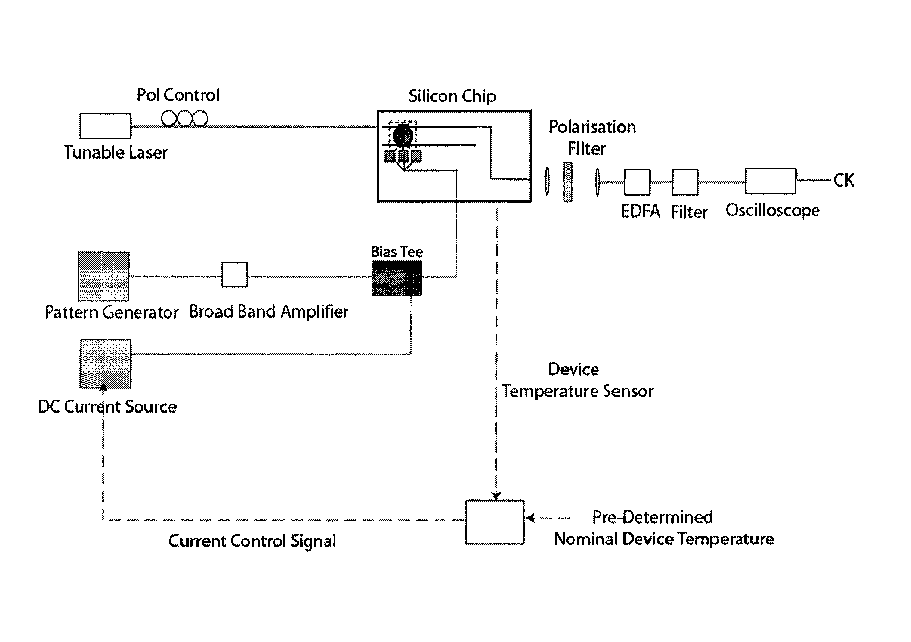
[0152]This example demonstrates high bit rate electro-optic modulation in a resonant micrometer-scale silicon modulator over an ambient temperature range of 15 K. Low bit error rates can be achieved by varying the bias current through the device to thermally counteract the ambient temperature changes. Robustness in the presence of thermal variations can enable a wide variety of applications for dense on chip electronic photonic integration.

[0153]This example also demonstrates that the effect of thermal variations on resonant electro-optic modulators can be locally compensated by adjusting the bias current passing through the device. The bias current through the device was varied to compensate for changes in the ambient temperature that affect the resonator. Low bit error rate (BER) modulation was maintained over a temperature range of 15 K. Robustness in the presence of environmental co...


PUM

PropertyMeasurementUnit
separating wavelengthaaaaaaaaaa
temperatureaaaaaaaaaa

Abstract

A thermally stabilized, high speed, micrometer-scale silicon electro-optic modulator is provided. Methods for maintaining desired temperatures in electro-optic modulators are also provided. The methods can be used to maintain high quality modulation in the presence of thermal variations from the surroundings. Direct current injection into the thermally stabilized electro-optic modulator is used to maintain the modulation performance of the modulator. The direct injected current changes the local temperature of the thermally stabilized electro-optic modulator to maintain its operation over a wide temperature range.

Description

CROSS-REFERENCE TO RELATED APPLICATIONS[0001]This application claims priority to and the benefit of co-pending U.S. provisional patent application Ser. No. 61 / 161,871 entitled “Method and apparatus for wide temperature range operation of micrometer-scale silicon electro-optic modulators,” by S. Manipatruni et al., filed Mar. 20, 2009, which is incorporated herein by reference in its entirety.STATEMENT REGARDING FEDERALLY SPONSORED RESEARCH OR DEVELOPMENT[0002]The disclosed invention was made with government support under contract no. W911NF-06-1-0057 from the Defense Advanced Research Projects Agency (DARPA), U.S. Army Research Office (ARO); contract no. W911NF-07-1-0652 from the U.S. Army Research Laboratory (ARL); and contract nos. 0446571 and 0347649 from the National Science Foundation CAREER Grant program. The government has rights in this invention.TECHNICAL FIELD[0003]The present invention relates to thermally stabilized, high speed, micrometer-scale silicon electro-optic mod...

Claims


Application Information

Patent Timeline
Patent Type & Authority Patents(United States)
IPC IPC(8): G02F1/01G02F1/07G02B6/26G02F1/03
CPCG02F1/011G02F2202/105G02F2203/15G02F2203/21G02F2203/60
Inventor MANIPATRUNI, SASIKANTHDOKANIA, RAJEEVAPSEL, ALYSSA B.LIPSON, MICHAL
Owner CORNELL UNIVERSITY
Why Eureka
Try Eureka