Porous medium with increased hydrophobicity and method of manufacturing the same

a porous medium and hydrophobic technology, applied in the direction of sustainable manufacturing/processing, cell components, ways, etc., can solve the problems of increasing voltage loss, complex manufacturing process itself, and difficulty in uniform distribution of hydrophobic agents, and achieve the effect of increasing hydrophobicity

Active Publication Date: 2012-11-01
HYUNDAI MOTOR CO LTD +1
View PDF8 Cites 23 Cited by
  • Summary
  • Abstract
  • Description
  • Claims
  • Application Information

AI Technical Summary

Benefits of technology

[0018]The present invention provides a method for increasing hydrophobicity on

Problems solved by technology

However, when an excessive amount of water produced is not appropriately removed, “flooding” occurs at high current density, preventing the reactant gases from being efficiently supplied to the fuel cell and thereby increasing voltage loss [M. M. Saleh, T. Okajima, M. Hayase, F. Kitamura, T. Ohsaka, J. Power Sources, 167, 503 (2007)].
However, a wet chemical process has conventionally been used to impart hydrophobicity, and thus the manufacturing process itself is complicated and it is difficult to uniformly distribute the hydrophobic agent such as PTTE on the gas diffusion layer.

Method used


Image

  • Porous medium with increased hydrophobicity and method of manufacturing the same
  • Porous medium with increased hydrophobicity and method of manufacturing the same
  • Porous medium with increased hydrophobicity and method of manufacturing the same

Examples


example 1

Material for Microporous Layer with Increased Hydrophobicity

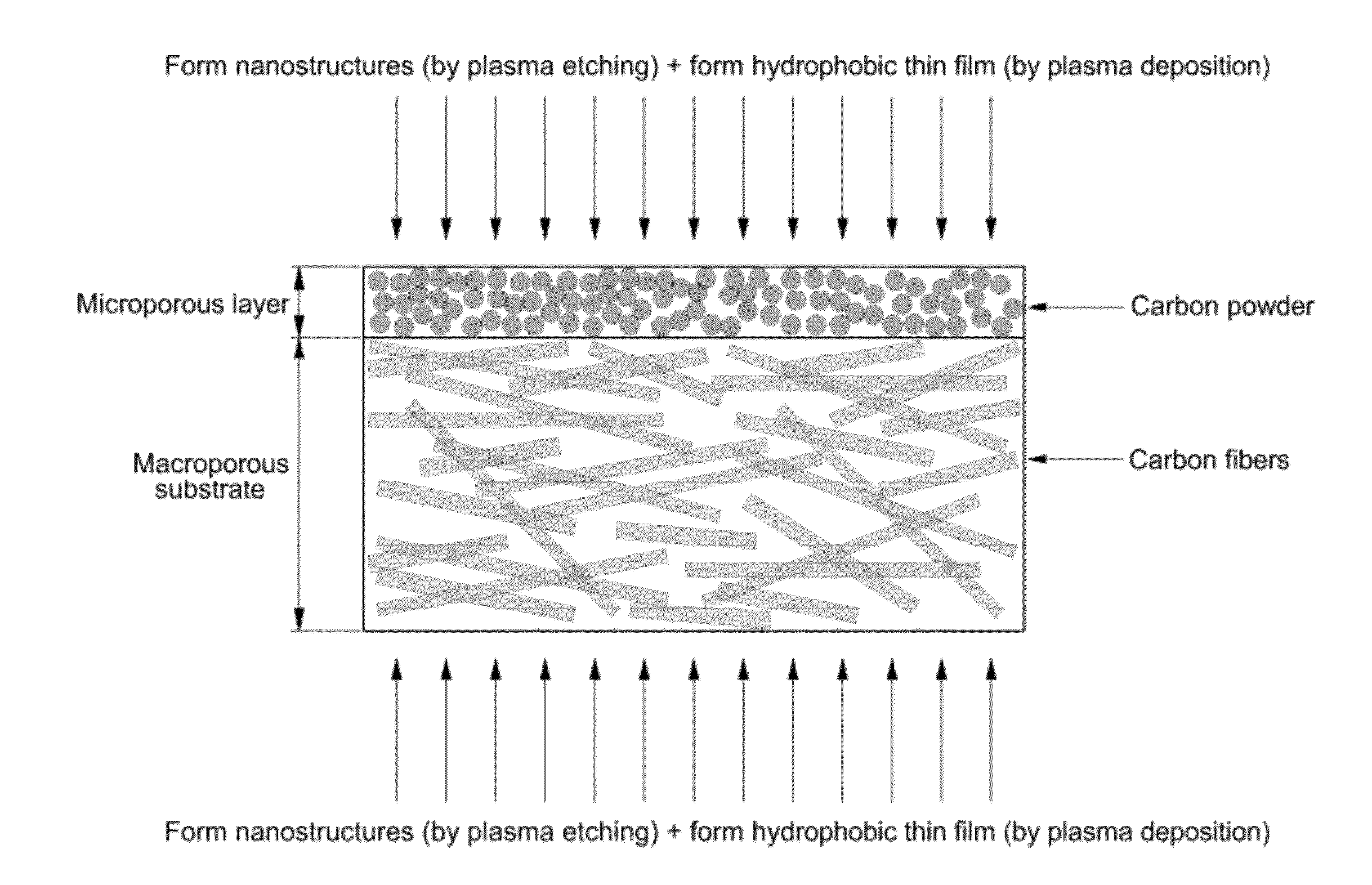
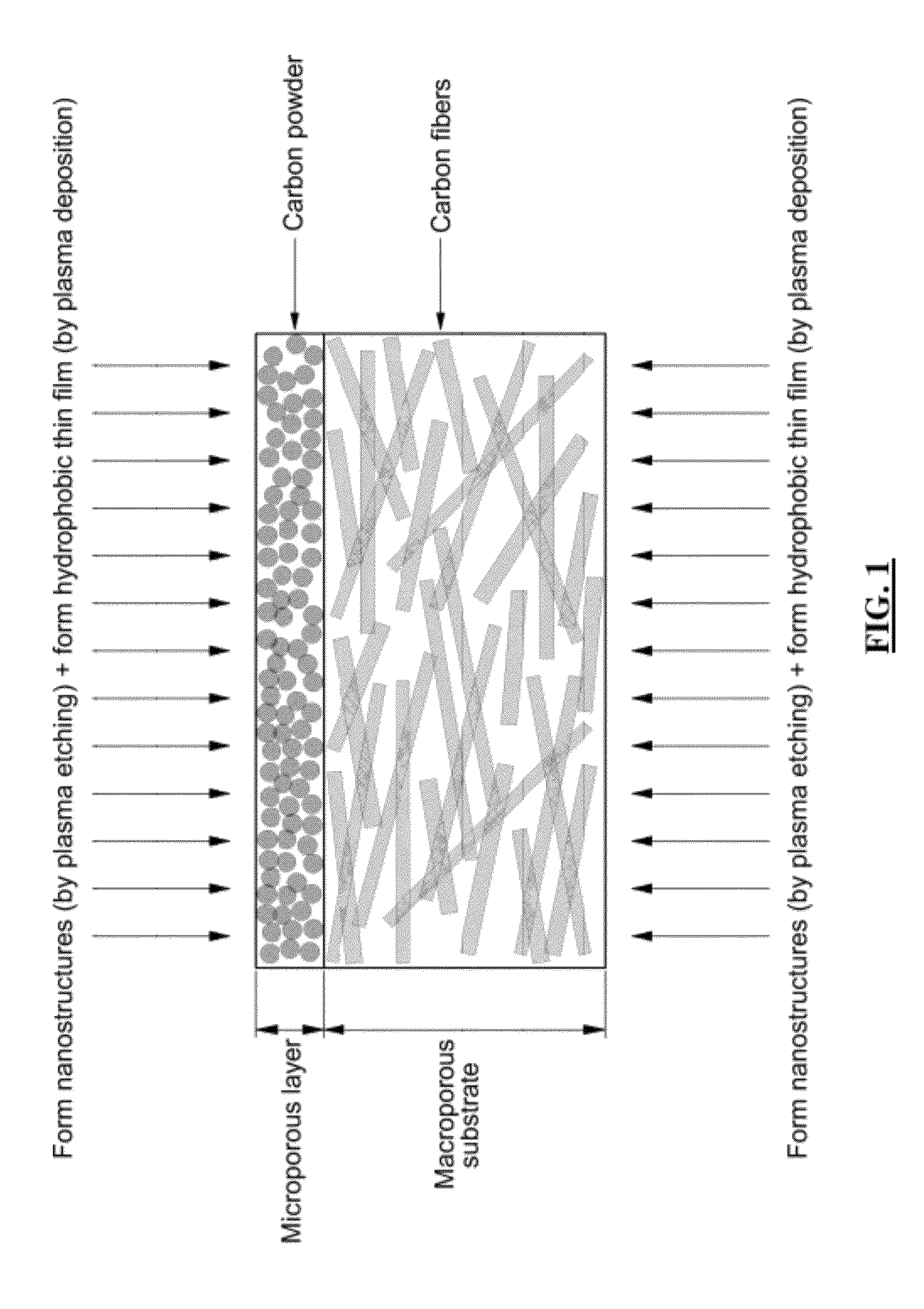
[0079]First, a commercially available gas diffusion layer material, which includes a microporous layer comprising carbon powder having a diameter of 10 to 300 nanometers and PTFE and a macroporous substrate comprising carbon fibers in the form of felt and PTFE, was used. However, a gas diffusion layer material with a macroporous substrate comprising only carbon fibers without a hydrophobic material such as PTFE may be applied to the present invention. The size of carbon particles forming the microporous layer in the gas diffusion layer material is not uniform and lies in the range of 10 to 300 nanometers.

[0080]The basic properties and characteristics of the gas diffusion layer used in this Example of the present invention are shown in Table 1. The entire thickness of the porous medium (i.e., gas diffusion layer) was obtained by the measurement of at least 20 times using a Mitutoyo thickness gauge (Mitutoyo Co., Japan).

[0081...

example 2

Material for Macroporous Substrate with Increased Hydrophobicity

[0093]The macroporous substrate on the other side (see FIG. 1) of the porous medium comprises carbon fibers in the form of felt and PTFE as a porous material interposed between the carbon fibers. Therefore, the contact angle of the macroporous substrate itself with respect to a droplet is about 135 to 145°. Moreover, the contact angle of the macroporous substrate is similar to that of the intrinsic microporous layer. The carbon fibers, which constitute the macroporous substrate, are provided in the form of felt, and the diameter of the carbon fibers are in the range of about 5 to 20 micrometers.

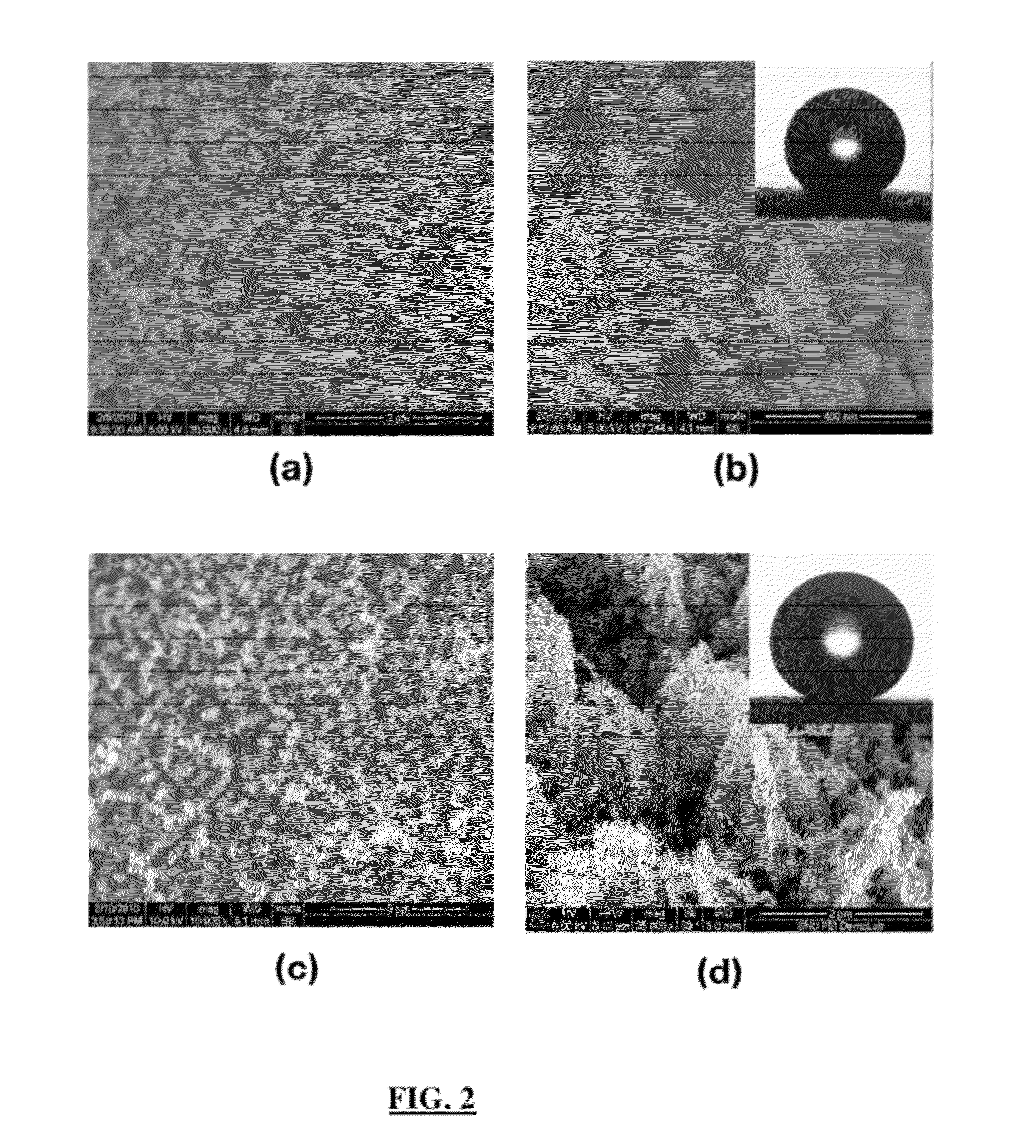
[0094]First, the surface of a prepared macroporous substrate was subjected to oxygen plasma etching treatment using RF-PECVD, and the oxygen plasma etching was performed under conditions where only oxygen was used as gas, the etching pressure was 10 Pa, and the RF voltage was −100 Vb to −800 Vb.

[0095]The oxygen plasma reacts with...


PUM

PropertyMeasurementUnit
Lengthaaaaaaaaaa
Lengthaaaaaaaaaa
Lengthaaaaaaaaaa

Abstract

The present invention provides a porous medium with increased hydrophobicity and a method of manufacturing the same, in which a micro-nano dual structure is provided by forming nanoprotrusions with a high aspect ratio by performing plasma etching on the surface of a porous medium with a micrometer-scale surface roughness and a hydrophobic thin film is deposited on the surface of the micro-nano dual structure, thus significantly increasing hydrophobicity. When this highly hydrophobic porous medium is used as a gas diffusion layer of a fuel cell, it is possible to efficiently discharge water produced during electrochemical reaction of the fuel cell, thus preventing flooding in the fuel cell. Moreover, it is possible to sufficiently supply reactant gases such as hydrogen and air (oxygen) to a membrane electrode assembly (MEA), thus improving the performance of the fuel cell.

Description

CROSS-REFERENCE TO RELATED APPLICATION[0001]This application claims under 35 U.S.C. §119(a) the benefit of Korean Patent Application No. 10-2011-0040477 filed Apr. 29, 2011, the entire contents of which are incorporated herein by reference.BACKGROUND[0002](a) Technical Field[0003]The present invention relates to a hydrophobic porous medium and a method of manufacturing the same. More particularly, it relates to a highly hydrophobic porous medium and a method of manufacturing the same.[0004](b) Background Art[0005]An electrochemical reaction in a polymer electrolyte membrane fuel cell (PEMFC) for electricity generation is as follows. Hydrogen supplied to an anode (“oxidation electrode”) in a membrane electrode assembly (MEA) of the fuel cell is dissociated into hydrogen ions (protons, H+) and electrons (e−). The hydrogen ions are transmitted to a cathode (“reduction electrode”) through a polymer electrolyte membrane, and the electrons are transmitted to the cathode through an externa...

Claims


Application Information

Patent Timeline
IPC IPC(8): B32B5/18B05D3/10C23C16/50B32B5/16C23F1/00B82Y30/00B82Y40/00
CPCH01M8/0234H01M8/0239H01M8/0243H01M8/0245Y10S977/89Y02E60/50Y10T428/24372Y10S977/778H01M8/04156Y02P70/50H01M4/86H01M8/02H01M8/10B32B2307/73B82Y40/00H01M2008/1095
Inventor HONG, BO KIKIM, SAE HOONLEE, KWANG RYEOLMOON, MYOUNG WOON
Owner HYUNDAI MOTOR CO LTD
Why Eureka
Try Eureka