Array of abrasive members with resilient support

a technology of resilient support and abrasive components, which is applied in the field of abrasive articles, can solve the problems of loss of head media spacing, roughness at the rounded areas, and magnetic damage due to etching of magnetic materials

Inactive Publication Date: 2010-11-04
RDC HLDG
View PDF99 Cites 24 Cited by
  • Summary
  • Abstract
  • Description
  • Claims
  • Application Information

AI Technical Summary

Benefits of technology

[0014]The preload mechanism is optionally a plurality of a metallic spring members embedded in one or more of the elastomeric support or the abrasive members. The preload mechanism can retain the abrasive members in a cantilevered relationship relative to the elastomeric support.

Problems solved by technology

Semiconductor wafers are typically fabricated using photolithography, which is adversely affected by inconsistencies or unevenness in the wafer surface.
Note that the tops of the bits are rounded, leading to head media spacing loss, roughness at the rounded areas, and magnetic damage due to etching of magnetic materials.
Such bits are not viable for magnetic recording.
The uneven material increases head media spacing and potential damage to the diamond-like-carbon overcoats.
CMP processes have proven inadequate to achieving smooth and flat tops both before and after magnetic material deposition.
Roughness and waviness is typically caused by uneven pressure applied by the pad during the polishing process.
Soft pad polishing of heterogeneous layered materials, such as semiconductor devices, causes differential removal and damage to the electrical devices.
Unfortunately, wear, hardness, uneven distribution of abrasive particles, and other characteristics of the CMP pad may change over the course of a given CMP process.
This accumulation causes a “glazing” or hardening of the top of the pad, thus making the pad less able to hold the abrasive particles of the slurry and decreasing the pad's overall polishing performance.
Further, with many pads the pores used to hold the slurry become clogged, and the overall asperity of the pad's polishing surface becomes depressed and matted.
The sub-micron particles used in CMP tend to agglomerate and strongly adhere to each other and to the substrate, resulting in nano-scale surface defects.
Once surface debris form on a substrate it is very difficult to effectively remove them using conventional cleaning methods.
), all of which are incorporated by reference, but have proven inadequate for the next generation semiconductors and magnetic media.
The incremental improvements in each of these disciplines have not kept pace with the shrinking feature size of features demanded by the electronics industry.

Method used


Image

  • Array of abrasive members with resilient support
  • Array of abrasive members with resilient support
  • Array of abrasive members with resilient support

Examples


example 1

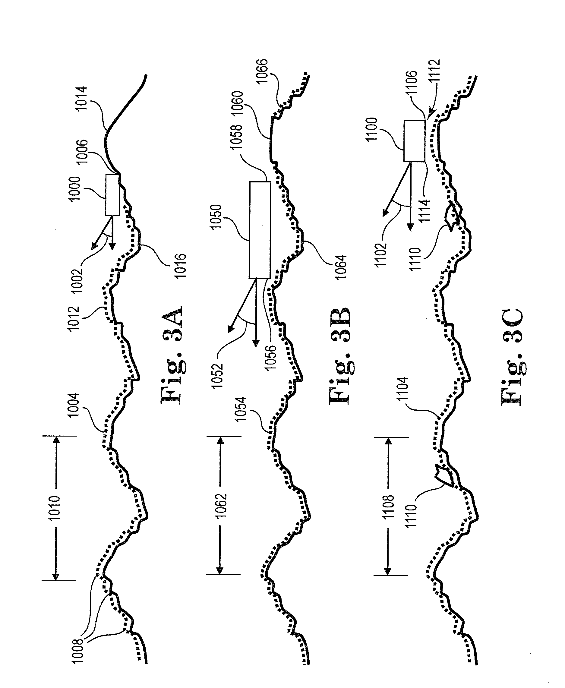
[0211]FIG. 47A illustrates an abrasive member 800 modeled for topography following applications. The leading edge 802 includes a plurality of discrete features 804 separated by cavities 806 that permit air flow and particles to enter. The cavity depth 812 is about 2 micrometers to about 3 micrometers to promote a negative suction force.

[0212]The leading edge pads 804 are formed with rounded surfaces 816 to promote the redistribution of debris and lubricant. This example of a low contact force abrasive member 800 includes leading edge step 818 that increases lift at the leading edge 802.

[0213]FIG. 47B is a graphical illustration of the contact pressure of the abrasive member 800 with the substrate. The leading edge pressure 802A is preferably zero. Trailing edge pressure 810A shows a minor negative suction force. Upon application of large loads (e.g., up to 12 grams) the leading edge 802 does not contact the substrate, while the trailing edge 810 follows the topography of the substra...

example 2

[0215]FIG. 48A illustrates an abrasive member 820 modeled for topography following applications. The leading edge 822 includes a plurality of discrete features 824 separated by slots 826 that permit air flow and particles to enter. This example of a low contact force abrasive member 820 includes leading edge step 828 and extended sides 830 to increase the negative pressure force (suction force). The leading edge step 828 has a depth of about 0.1 micrometers to about 0.5 micrometers to promote the formation of higher pressure at the leading edge 822. Note that the trailing edge 832 is formed of discrete pads 834 to reduce the spacing between the substrate and the abrasive member, and to allow for circulation of lubricant and debris.

[0216]FIG. 48B is a graphical illustration of the contact pressure for the abrasive member 820 against the substrate. The contact forces are concentrated at the pads 834 located at trailing edge 832. The negative pressure saturates around 3.5 grams while t...

example 3

[0218]FIG. 49A illustrates an abrasive member 840 modeled for topography removing applications. The leading edge 842 includes a plurality of discrete features 844 separated by slots 846 that permit air flow and particles to enter. The trailing edge 848 similarly includes a plurality of discrete features 850 separated by slots 852. The features 844, 850 have a height 854 of about 2 micrometers and are formed with rounded leading edge surfaces to distribute both lubricant and wear debris.

[0219]The height 854 is sufficient to create a positive pressure profile at the top of the pads 844, 850 and a negative suction force at the trailing side 845 of the features 844 in cases of air as a lubricant. The proper selection of the pressure distributions controls the pitch angle of the abrasive member 840 and the minimum spacing above the substrate.

[0220]In the case of topography removing, the abrasive member 840 does not follow certain target wavelengths of waviness. The pitch angle of the abr...


PUM

PropertyMeasurementUnit
peak-to-valley roughnessaaaaaaaaaa
roughnessaaaaaaaaaa

Abstract

An abrasive article having an array of abrasive members with an elastomeric support that permits each abrasive member to move independently in at least pitch and roll. Each abrasive member maintains a fluid bearing (air is the typical fluid) with the substrate. The abrasive members are capable of selectively engaging with nanometer-scale and / or micrometer-scale height variations and micrometer-scale and / or millimeter-scale wavelengths of waviness, on the surfaces of substrates. The spacing and pitch of the abrasive members can be adjusted to follow the topography of the substrate to remove a generally uniform layer of material; to engage with the peaks on the substrate to remove target wavelengths of waviness; and / or to remove debris and contamination from the surface of the substrate.

Description

RELATED APPLICATIONS[0001]The present application is a continuation-in-part of U.S. application Ser. No. 12 / 766,473, entitled Abrasive Article with Array of Gimballed Abrasive Members and Method of Use, filed Apr. 23, 2010, which claims the benefit of U.S. Provisional Patent Application Nos. 61 / 174,472 entitled Method and Apparatus for Atomic Level Lapping, filed Apr. 30, 2009; 61 / 187,658 entitled Abrasive Member with Uniform Height Abrasive Particles, filed Jun. 16, 2009; 61 / 220,149 entitled Constant Clearance Plate for Embedding Diamonds into Lapping Plates, filed Jun. 24, 2009; 61 / 221,554 entitled Abrasive Article with Array of Gimballed Abrasive Members and Method of Use, filed Jun. 30, 2009; 61 / 232,425 entitled Constant Clearance Plate for Embedding Abrasive Particles into Substrates, filed Aug. 8, 2009; 61 / 232,525 entitled Method and Apparatus for Ultrasonic Polishing, filed Aug. 10, 2009; 61 / 248,194 entitled Method and Apparatus for Nano-Scale Cleaning, filed Oct. 2, 2009; 61...

Claims


Application Information

Patent Timeline
Patent Type & Authority Applications(United States)
IPC IPC(8): B24B1/00B24B41/02
CPCY10T29/5397B24D11/00
Inventor SCHWAPPACH, KARL G.
Owner RDC HLDG
Why Eureka
Try Eureka