High capacity thin module system and method

A circuit module and type technology, which is applied in the structural connection of printed circuits, printed circuit components, etc., can solve problems such as deterioration of heat dissipation characteristics of DIMM circuit modules.

Inactive Publication Date: 2008-06-25
STAKTEK GROUP LP
View PDF1 Cites 10 Cited by
  • Summary
  • Abstract
  • Description
  • Claims
  • Application Information

AI Technical Summary

Problems solved by technology

As a result, in a typical FB-DIMM, the already critical heat dissipation characterist

Method used


Image

  • High capacity thin module system and method
  • High capacity thin module system and method
  • High capacity thin module system and method

Examples


Embodiment Construction

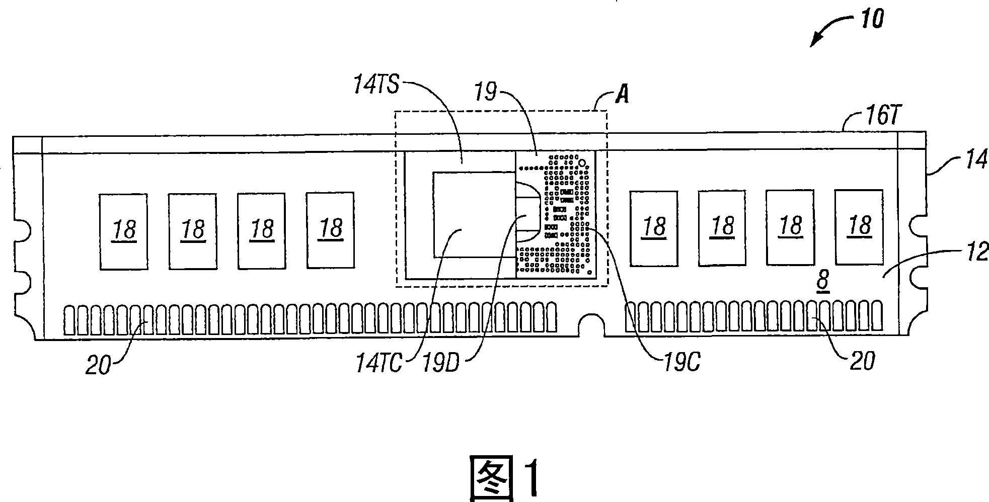
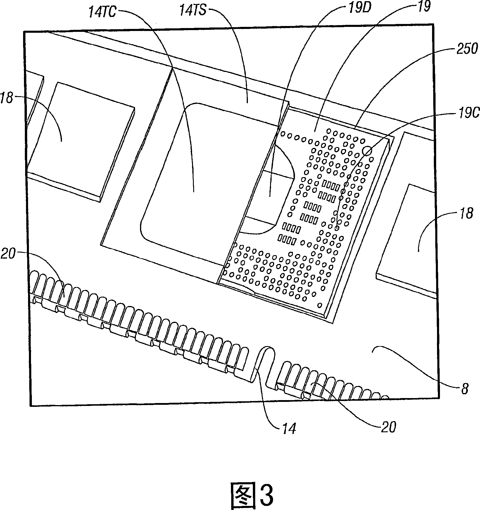
[0025] Figure 1 shows a module 10 designed in accordance with a preferred embodiment of the present invention. The diagram of FIG. 1 shows a module 10 having a substrate 14 near which is disposed a flex circuit 12 populated with an IC 18 which in a preferred embodiment is a memory device within a CSP package . Flex circuit 12 is shown in cross-section in area "A" to illustrate preferred features of the interior of module 10 . Area "A" is shown more enlarged in FIG. 3 below.

[0026] Heat sink 14TS is visible in area A, and in section beyond heat sink 14TS is shown a portion of circuitry 19 which, in the preferred embodiment, is a well-known advanced Memory Buffer or AMB. AMB circuit 19 includes AMB die 19D and contacts 19C. Typically, for example, a module according to a preferred embodiment will show a plurality of CSPs of a first type, such as a memory CSP, and will have at least one CSP of a second type, such as a microprocessor, graphics processor, or buffer, or More ...


PUM


Abstract

Flexible circuitry is populated with integrated circuitry disposed along one or both of its major sides. Contacts distributed along the flexible circuitry provide connection between the module and an application environment. The circuit-populated flexible circuitry is disposed about an edge of a rigid substrate thus placing the integrated circuitry on one or both sides of the substrate with one or two layers of integrated circuitry on one or both sides of the substrate. The substrate form is preferably devised from thermally conductive materials and includes a high thermal conductivity core or area that is disposed proximal to higher thermal energy devices such as an AMB when the flex circuit is brought about the substrate. Other variations include thermally-conductive clips that grasp respective ICs on opposite sides of the module to further shunt heat from the ICs. Preferred extensions from the substrate body or substrate core encourage reduced thermal variations amongst the integrated circuits of the module.

Description

technical field [0001] The present invention relates to systems and methods for creating high density circuit modules, and more particularly to systems and methods for creating modules with features designed to reduce thermal load concentrations. Background technique [0002] Memory expansion is one of many areas where high-density circuit module solutions offer space-saving advantages. For example, the well-known DIMM (Dual In-line Memory Module, Dual In-line Memory Module) has been used in various forms for many years to provide memory expansion. A typical DIMM includes a conventional PCB (printed circuit board) with memory devices and supporting digital logic devices mounted on both sides. Typically, a DIMM is installed within the host computer system by inserting the contact support edge of the DIMM into the card edge connector. Typically, systems employing DIMMs offer limited form factor space for such devices, and traditional DIMM-based solutions typically offer only...

Claims


Application Information

Patent Timeline
IPC IPC(8): H05K1/14
Inventor J・D・小韦尔利J・怀尔德P・古德温M・沃尔夫
Owner STAKTEK GROUP LP
Why Eureka
Try Eureka