Switching voltage regulator with negative temperature compensation

a voltage regulator and temperature compensation technology, applied in the direction of electric variable regulation, power conversion systems, instruments, etc., can solve the problems of high cost of all appliances, non-respect of some load specifications, and compromise of high precision

Active Publication Date: 2006-02-14
STMICROELECTRONICS SRL
View PDF11 Cites 11 Cited by
  • Summary
  • Abstract
  • Description
  • Claims
  • Application Information

AI Technical Summary

Benefits of technology

[0009]In one embodiment the MOS transistor includes a non-drivable terminal coupled with said output terminal and a control circuit receiving a signal that is representative of the current signal flowing in said MOS tra

Problems solved by technology

This may bring to non-respect of some specifications of the loads such as the microprocessors.
Such resistors have thermal variations lower than the resistance Rdson, are very precise but the high precision thereof is compromised by the high co

Method used


Image

  • Switching voltage regulator with negative temperature compensation
  • Switching voltage regulator with negative temperature compensation
  • Switching voltage regulator with negative temperature compensation

Examples


Embodiment Construction

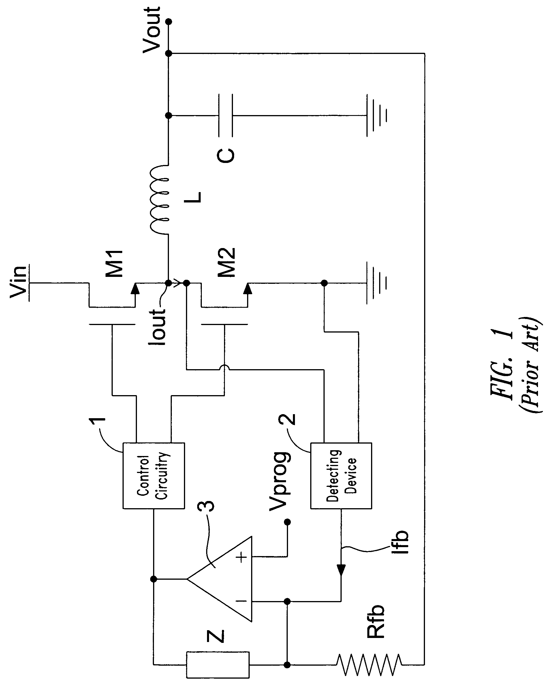
[0020]Referring to FIG. 1 a switching regulator according to the prior art is shown; said regulator comprises two MOS power transistors M1 and M2 where the source terminal of the transistor M1 is in common with the drain terminal of the transistor M2 and it is connected with an inductance L the other terminal of which is the output terminal of the regulator. The drain terminal of the transistor M1 is connected with an input voltage Vin while the source terminal of the transistor M2 is connected to ground. The gate terminals of the transistors M1 and M2 (which may constitute even the electric equivalent of more MOS transistors connected with each others in parallel) are driven by means of a control circuitry 1. The transistors M1 and M2 may be discrete components or may be integrated in the same chip with the control circuitry 1. The current flowing between the drain and source terminals of the transistor M2 is detected by means of a detecting device 2 that preferably comprises an am...


PUM


Abstract

A switching voltage regulator provides a regulated voltage at an output terminal. The switching voltage regulator includes a MOS transistor having a non-drivable terminal coupled with the output terminal and a control circuit receiving a signal that is representative of the current signal flowing in the MOS transistor. The control circuit includes a compensation device adapted for cancelling the thermal variation of the signal that is representative of the current signal flowing in the MOS transistor.

Description

TECHNICAL FIELD[0001]The present invention refers to a switching voltage regulator.BACKGROUND OF THE INVENTION[0002]It is usually known the use of control circuits in switching static regulators employed in power suppliers wherein particular features on the precision of the regulation are requested, as in the power supply circuits of the high performance modern microprocessors. Particularly such power suppliers must provide higher and higher currents and lower and lower voltages.[0003]Switching regulators are used to perform said power suppliers. Each regulator comprises at least one MOS power transistor; particularly some regulators comprise a pair of MOS transistors or several pairs of MOS transistors which are arranged in parallel to each others and which are connected with a single output terminal by means of an inductance for each transistor pair (Multi-phase converters). The output currents of said pairs of transistors are automatically balanced by means of a control operation...

Claims


Application Information

Patent Timeline
IPC IPC(8): G05F1/40H02M3/156
CPCH02M3/156H02M2001/0025H02M2001/0009H02M1/0009H02M1/0025
Inventor GATTAVARI, GIUSEPPEVAI, RAIMONDO
Owner STMICROELECTRONICS SRL
Why Eureka
Try Eureka