Precise temperature sensor with smart programmable calibration

a temperature sensor and smart technology, applied in the field of temperature stabilized sub1v bandgap reference voltage circuits, can solve the problems of complex and expensive circuits, inability to provide programmable calibration, and difficulty in approaching a stable operation in conventional bandgap reference circuits. achieve the effect of simple calibration

Active Publication Date: 2007-04-17
ETRON TECH INC
View PDF11 Cites 38 Cited by
  • Summary
  • Abstract
  • Description
  • Claims
  • Application Information

AI Technical Summary

Benefits of technology

[0011]It is another object of the present invention to provide a plurality of temperature sensors with selectable spacing between temperature points with simple calibration.

Problems solved by technology

However, it is difficult to approach a stable operation in conventional bandgap reference (BGR) circuits when the supply voltage is under 1.5 V.
This is a complex and expensive circuit using a lot of chip real estate, but does not provide programmable calibration.
However the circuit is not capable of providing multiple temperature outputs with programmable calibration.
This circuit provides calibration but no programming capability for multiple temperature point outputs.

Method used


Image

  • Precise temperature sensor with smart programmable calibration
  • Precise temperature sensor with smart programmable calibration
  • Precise temperature sensor with smart programmable calibration

Examples


Embodiment Construction

[0022]Circuits 100 of FIG. 1a, 200 of FIG. 1b, and 300 of FIG. 1c comprise the preferred embodiment of a precise temperature sensor with smart calibration.

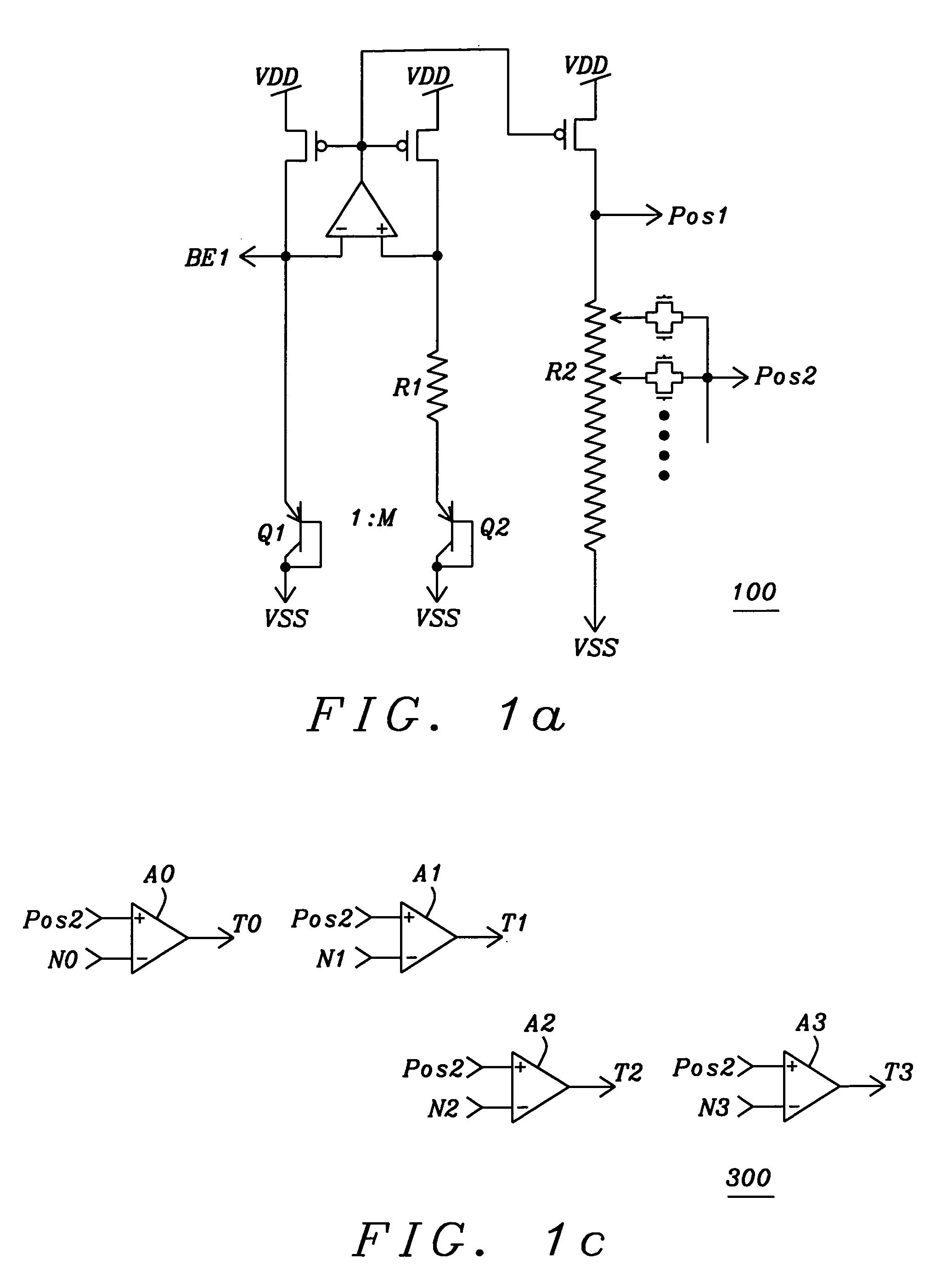
[0023]FIG. 100 is a bandgap reference circuit identical to the referenced Related Patent Application with the exception that resistor R2 is a programmable resistor which can be programmed by the different pass-gates as indicated. The common output node of these pass-gates is Pos2 and provides a voltage VPos2. When programmed, the resistance seen between node Pos2 and VSS is designated as R2′. Former node POS is relabeled Pos1 and provides voltage VPos1.

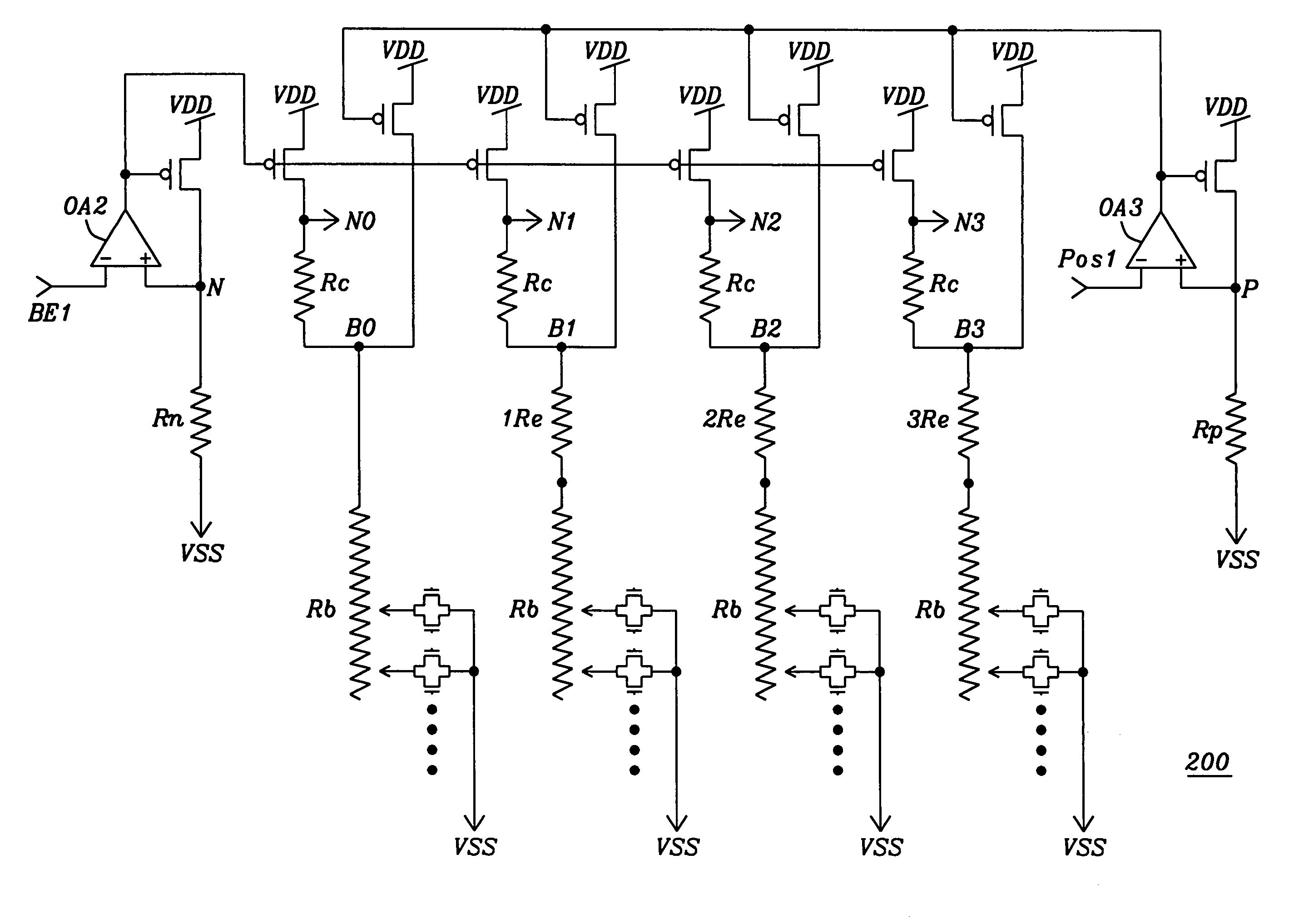
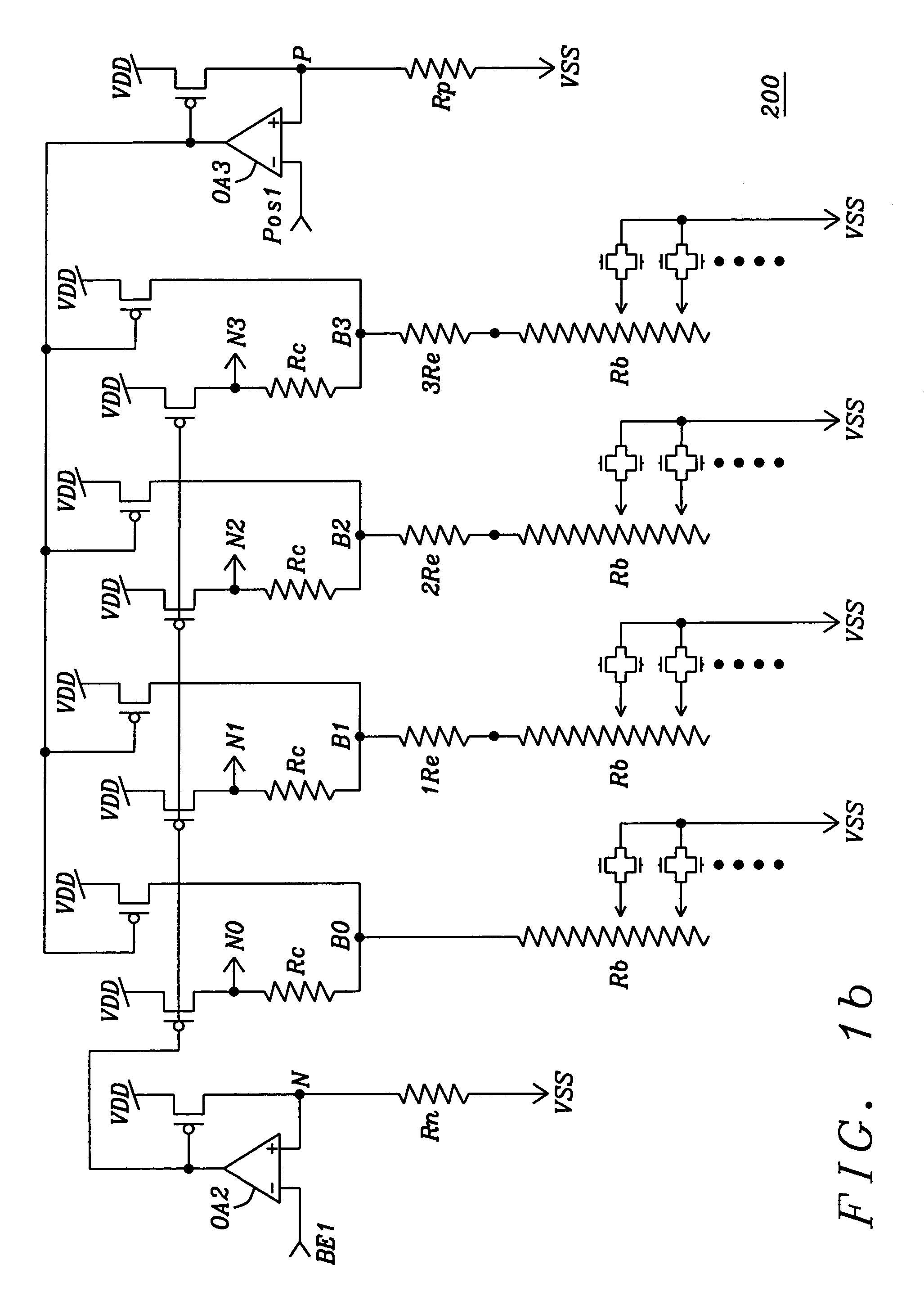
[0024]Circuit 200 is similar to the summing circuit of the Related Patent Application, including the connections to circuit 100, but has been expanded to provide means for e.g. four temperature sensors 210, 211, 212, and 213, and the single current mirror driven by each by the outputs of op-amps OA2, OA3 was increased to four each. Resistor Rn (at node N) and resistor Rp (at node P)...


PUM

PropertyMeasurementUnit
temperature coefficientaaaaaaaaaa
currentaaaaaaaaaa
reference voltageaaaaaaaaaa

Abstract

A temperature sensor with a plurality of temperature sense points based on a bandgap reference circuit providing negative temperature coefficient reference voltages and a positive temperature coefficient reference voltage. All negative temperature coefficient reference voltages have the same slope and the same spacing from each other. The intercept points between the negative temperature coefficient reference voltages and the positive temperature coefficient reference voltage determine the temperature sense points. Efficient calibration of the spacing of the temperature sense points is provided by a tap on a programmable resistor in the positive temperature coefficient reference circuit. Efficient calibration of the absolute temperature is provided by second programmable resistors in a circuit driven by two current sources. The calibration of one temperature point equally applies to all other second programmable resistors.

Description

RELATED PATENT APPLICATION[0001]ET04-010, LOW VOLTAGE BANDGAP REFERENCE (BGR) CIRCUIT, title filing date: Feb. 11, 2005, Ser. No. 11 / 056,796, assigned to a common assignee.BACKGROUND OF THE INVENTION[0002]1. Field of the Invention[0003]The invention relates to temperature-stabilized sub-1-V bandgap reference voltage circuits, and more particularly to a circuit using a low supply voltage with a plurality of temperature sensors. Programmable adjustable resistors are employed to calibrate the slope (span) and the absolute temperature.[0004]2. Description of the Related Art[0005]Temperature sensors with high precision based on bandgap reference (BGR) circuits which operate in the sub-1-V bandgap reference region using a low voltage power supply are necessary in many applications. Particularly desirable are circuits with multiple temperature sensors where the temperature sensors track each other very closely without requiring complex and extensive circuits placing undue demands on expens...

Claims


Application Information

Patent Timeline
Patent Type & Authority Patents(United States)
IPC IPC(8): G01K7/01G01K15/00G01K7/14G01K7/21
CPCG01K7/01G01K15/00
Inventor HSU, JENSHOU
Owner ETRON TECH INC
Why Eureka
Try Eureka