Temperature sensor
a temperature sensor and sensor technology, applied in the field of temperature sensors, can solve the problems of destroying the temperature range for accurately extracting the ptap voltage is limited, and the integrated circuit of the semiconductor will be destroyed, so as to achieve stable operation and easy adjustment
- Summary
- Abstract
- Description
- Claims
- Application Information
AI Technical Summary
Benefits of technology
Problems solved by technology
Method used
Image
Examples
first embodiment
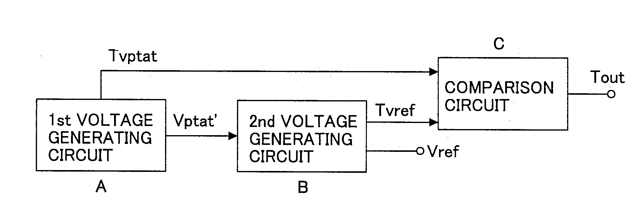
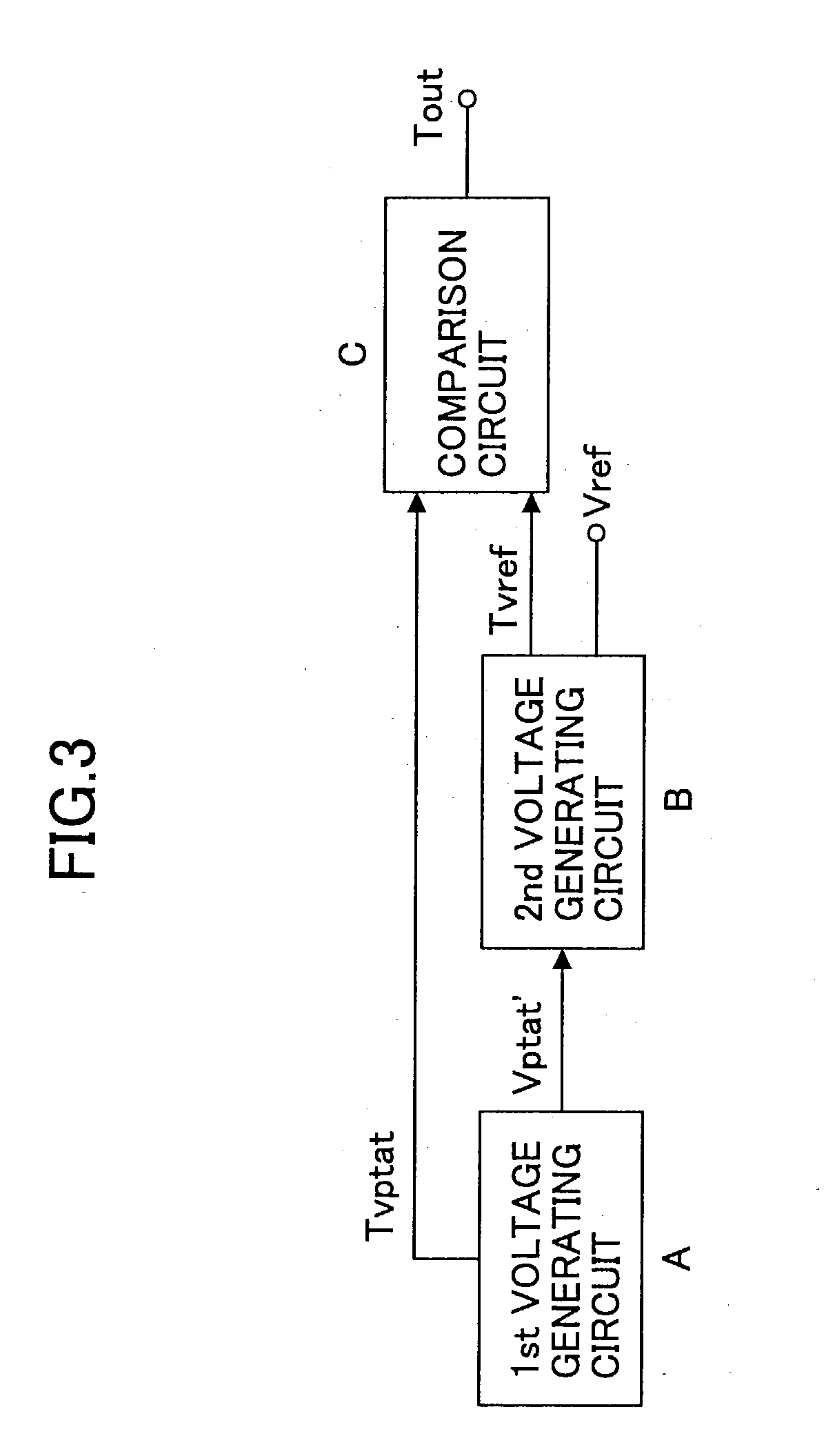
[0084] FIG. 8 illustrates a modification of the temperature sensor of the In the modification, the temperature sensor is formed on a p-type substrate. The temperatures sensor comprises a first voltage generating circuit, a second voltage generating circuit, and a comparison circuit, as in the circuit shown in FIG. 4.
[0085] The first voltage generating circuit comprises p-type transistors M1, M2, and M3, and resistors R6, R7 and R8. Transistors M1 and M2 are formed in the n-type well of the p-type substrate, and have the same impurity concentration at the channel regions and the source / drain regions. The electric potential of the substrate of each transistor is equal to the source potential. The ratios (W / L) of the channel width W to the channel length L of the transistors M1 and M2 are set equal. Transistor M2 has a lightly-doped n-type gate, and it is used as a constant current source with the gate connected to its source.
[0086] Transistor M1 has a highly doped n-type gate, and it...
second embodiment
[0112] In the second embodiment, the second voltage generating circuit makes use of the principle of difference in gate work function, while the first voltage generating circuit may or may not utilize the difference of gate work function.
[0113] FIG. 13 is a circuit diagram of the temperature circuit shown in FIG. 12. This circuit is formed in an n-type substrate. The first voltage generating circuit is comprised of an NPN transistor Tr1. The base of Tr1 is coupled to its collector, and the emitter is connected to the ground voltage GND, thereby outputting Svptat from the collector. The NPN transistor Tr1 can be fabricated by forming a base connected to the p-type well formed in the n-type substrate, and forming an emitter and a collector connected to the n-type diffusion layers formed in the p-type well.
[0114] The second voltage generating circuit is comprised of a first reference voltage generating circuit and a second reference voltage generating circuit. The first reference volta...
third embodiment
[0189] FIG. 20 is a circuit diagram of a modification of the temperature sensor according to the invention. This circuit is fabricated in an n-type substrate.
[0190] The first voltage generating circuit comprises n-type transistors M1, M2, and M3, and resistors R1, R2 and R3. Transistors M1 and M2 are formed-in the p-type well of the n-type substrate, and have the same impurity concentration at the channel regions and the source / drain regions. The electric potential of the substrate of each transistor is equal to the source potential. The n-type transistor M1 has a highly-doped n-type gate, and n-type transistor M2 has a lightly-doped n-type gate. The ratios (W / L) of the channel width W to the channel length L of the transistors M1 and M2 are set equal to each other.
[0191] The transistors M1 and M2, which are substantially the same except for the impurity concentrations of the gates, are connected in series. The gate of transistor M1 is coupled to its source. Thus, the transistor M1 ...
PUM
 Abstract
Description
Claims
Application Information
 - R&D
- Intellectual Property
- Life Sciences
- Materials
- Tech Scout
- Unparalleled Data Quality
- Higher Quality Content
- 60% Fewer Hallucinations
Browse by: Latest US Patents, China's latest patents, Technical Efficacy Thesaurus, Application Domain, Technology Topic, Popular Technical Reports.
© 2025 PatSnap. All rights reserved.Legal|Privacy policy|Modern Slavery Act Transparency Statement|Sitemap|About US| Contact US: help@patsnap.com


