Routing Device for Optical Fibre Systems

a routing device and optical fibre technology, applied in the direction of optics, instruments, optical light guides, etc., can solve the problem of poor routing below the minimum bend radius, and achieve the effect of preventing accidental removal of the routing device and quick installation

Inactive Publication Date: 2009-08-13
PRYSMIAN CABLES & SYST
View PDF8 Cites 5 Cited by
  • Summary
  • Abstract
  • Description
  • Claims
  • Application Information

AI Technical Summary

Benefits of technology

[0010]The Applicant has found that controlling the routing and distribution of optical fibres at an early stage in an optical hardware system, e.g. in an optical joint, can minimise congestion of cable elements, such as optical cables or transport tubes, and prevents, among other things, the above-mentioned optical fibre faults.

Problems solved by technology

The Applicant has in fact perceived that the solutions known in the art do not provide any control of the cable elements between the entry port of the joint and the entrance to the tray, this aspect being left to the installers discretion and possibly leading to congestion as well as poor routing below the minimum bend radius.

Method used


Image

  • Routing Device for Optical Fibre Systems
  • Routing Device for Optical Fibre Systems
  • Routing Device for Optical Fibre Systems

Examples


Embodiment Construction

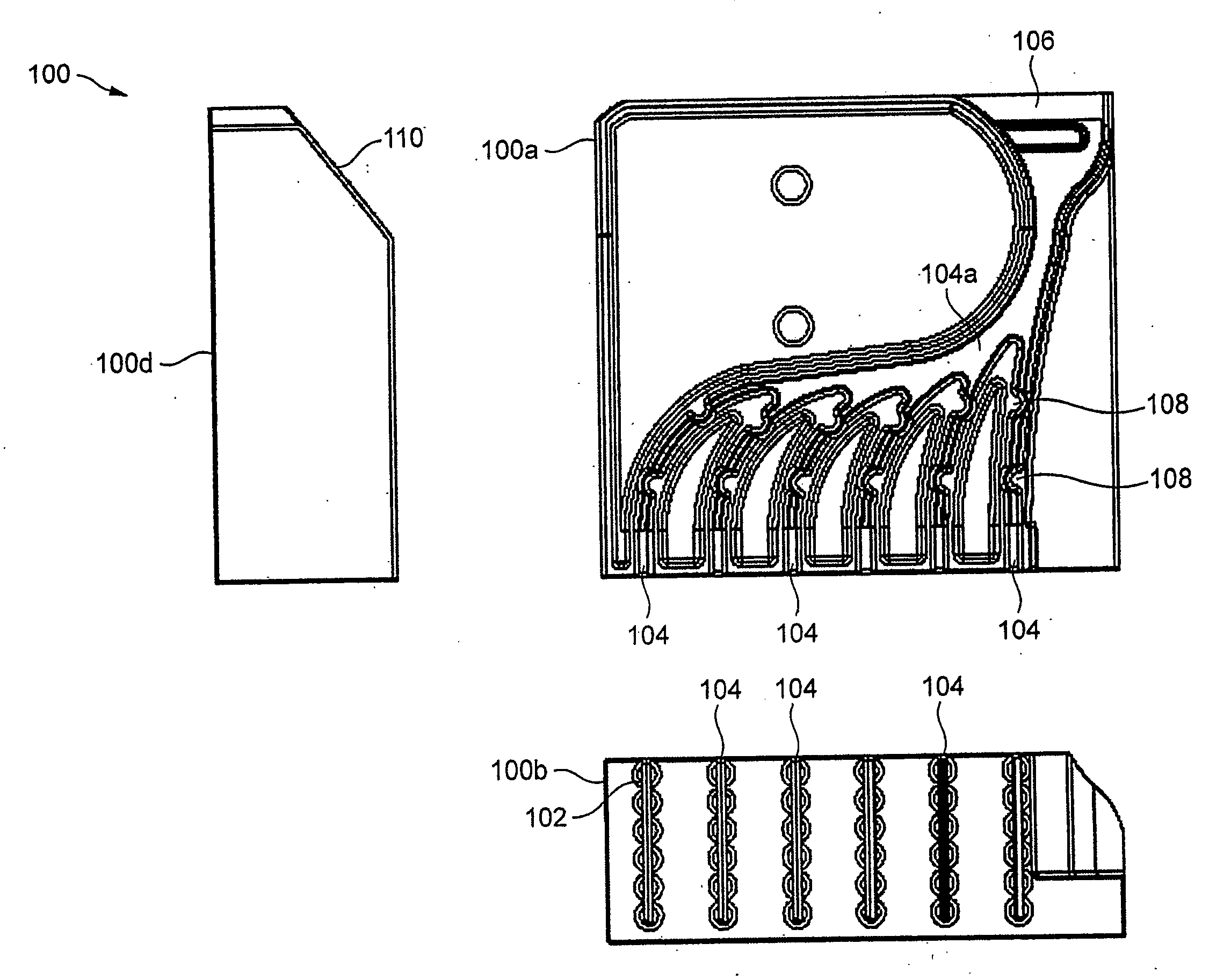
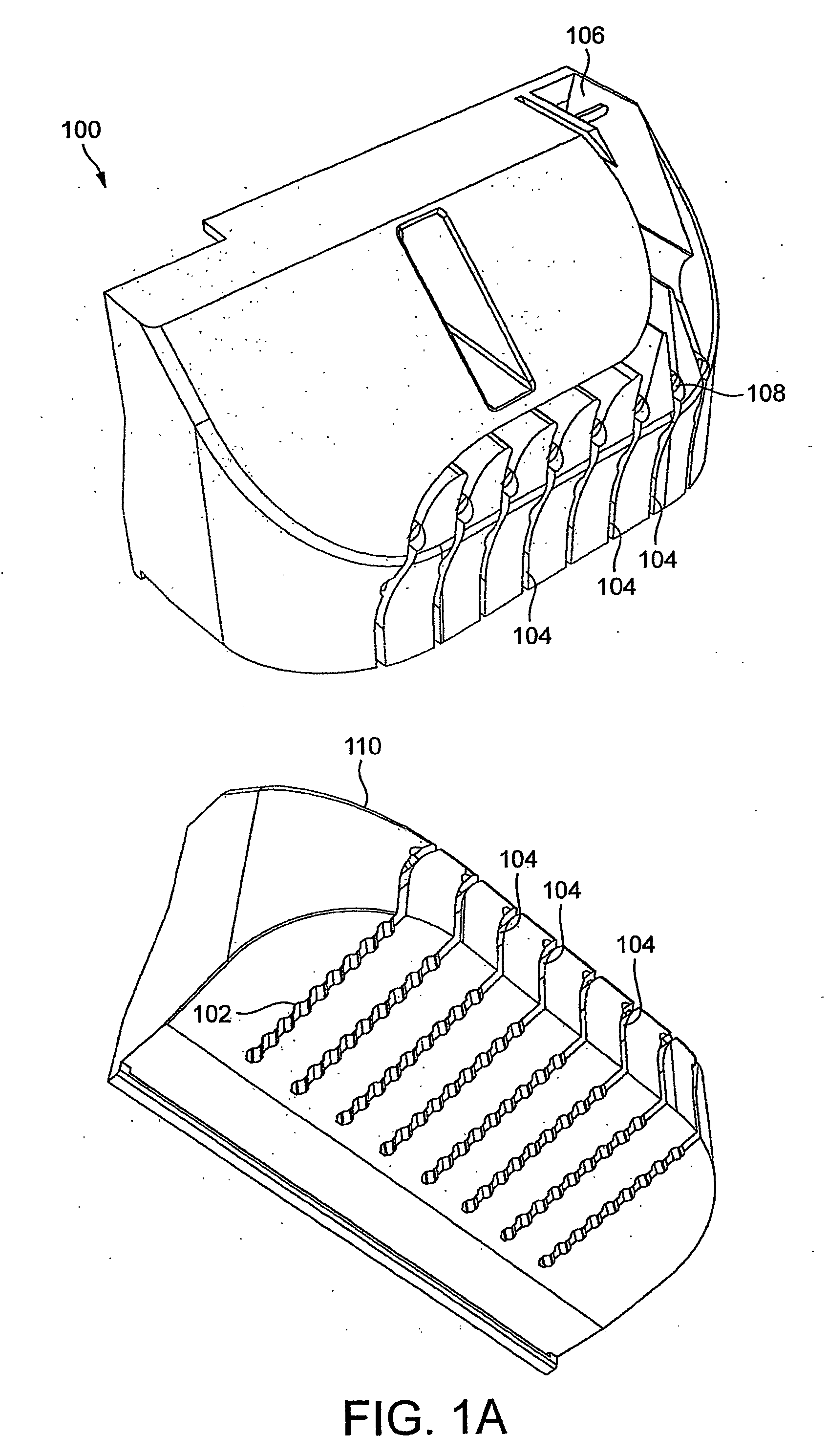
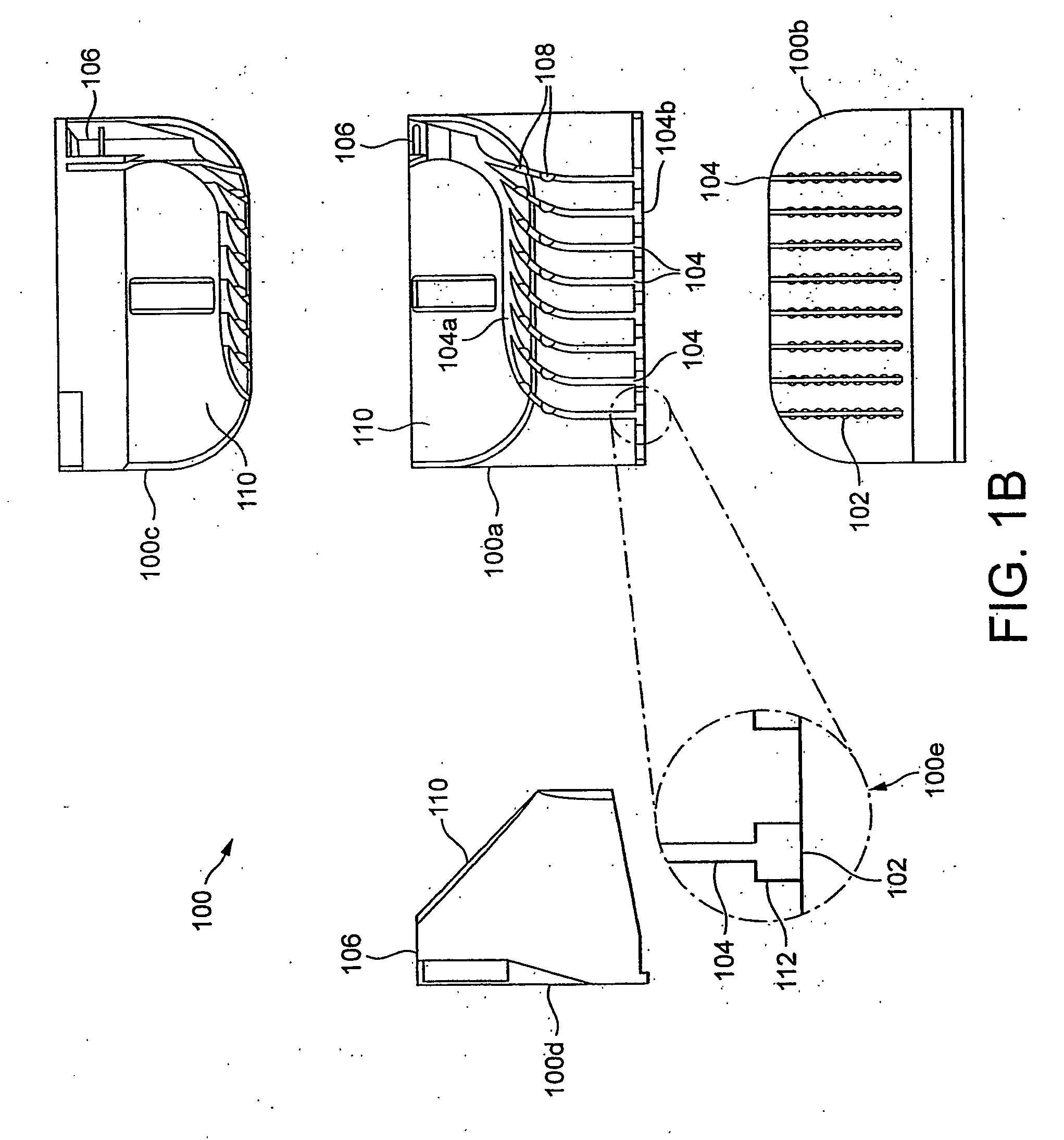
[0048]Two perspective views of a routing device 100 for routing and distributing optical fibres in an optical system is shown in FIG. 1a A plan elevation 100a, front elevation 100b, back elevation 100c, and side elevation 100d of the routing device 100 is shown in FIG. 1b. In addition, a plan elevation 100a, front elevation 100b, and side elevation 100d of a further arrangement of the routing device 100 is also shown in FIG. 1c.

[0049]Referring to FIGS. 1a, 1b and 1c, a brief overview of the routing device 100 is now given followed by a detailed description of its components and use. The routing device 100 includes a plurality of cable ports 102 that are connected to a plurality of guiding tracks 104, which connect from the cable ports 102 to an output port 106. Tabs 108 are included on the routing device 100, and are located on and / or partially over the guiding tracks 104.

[0050]The routing device 100 provides a means for routing and distributing optical fibres in an optical system,...


PUM


Abstract

A routing device is provided for use in optical systems for routing and distributing optical fibres within optical networks, optical hardware, and optical joints thereof. The routing device includes a plurality of cable ports for receiving one or more cable elements, which include one or more optical fibres. Each of a plurality of guiding tracks is connected to at least one cable port, and one or more output ports in which the optical fibres are routed from the cable ports to the output ports. An optical joint for use in optical systems includes, one or more trays and at least one routing device mounted within the optical joint. The optical joint receives the one or more cable elements, which are plugged into the routing device and routes the one or more optical fibres through the routing device to distribute them from at least one of the output ports to their respective trays.

Description

FIELD OF THE INVENTION[0001]The present invention relates to a routing device for use in optical systems. In particular, it relates to the routing and distribution of optical fibres in optical networks, optical hardware, and optical joints thereof.BACKGROUND[0002]Optical communication systems require the laying down of numerous optical cables and fibres. These are connected to various forms of optical fibre hardware such as optical joints, e.g. optical fibre closures or splicing enclosures. Optical joints are used for managing optical cable and fibre connections and storage and provide a point in which optical fibres are spliced or stored and sealed from the environment.[0003]Typically, optical joints receive a plurality of optical cables, each in turn having at least one optical fibre. This generally causes congestion of the optical joints due to intertwining of the optical cables and / or of the optical fibres. As more optical cables and fibres are connected to an optical communicat...

Claims


Application Information

Patent Timeline
Patent Type & Authority Applications(United States)
IPC IPC(8): G02B6/00
CPCG02B6/4472G02B6/4442
Inventor GRIFFITHS, IANHUBBARD, PAULJONES, MALCOLM
Owner PRYSMIAN CABLES & SYST
Why Eureka
Try Eureka