
Remote Confined Work Space Monitoring System and Method

a remote monitoring and work space technology, applied in the direction of visible signalling system, television system, electric transmission signalling system, etc., can solve the problems of inability to meet the requirements of class b>1/b> specifications, inefficient system, etc., to reduce the volume of cabling and electrical connections, reduce weight, and reduce the effect of weigh

Inactive Publication Date: 2020-08-27
IMPACT SAFETY SOLUTIONS LTD
View PDF0 Cites 0 Cited by
  • Summary
  • Abstract
  • Description
  • Claims
  • Application Information

AI Technical Summary

Benefits of technology

The patent describes a system and method for remotely monitoring confined work spaces to improve safety and efficiency. The system includes a gas detection system and an automated access control system to manage congestion. It also uses RFID tagged badges for efficient monitoring of worker activity and improved work scheduling. The gas detection system can detect various gases, such as oxygen, carbon monoxide, carbon dioxide, and others. Overall, the system helps minimize human error, reduce risks, and achieve real-time measurements in confined work spaces.

Problems solved by technology

However, the person responsible for performing the safety watch is positioned outside the confined work space and is not allowed to break the plane of entrance to the confined work space.
As a result, all communication between the safety watch and the worker in the confined work space is performed verbally, which can create a very inefficient system as the safety watch does not have any visual feedback of the exact situation inside the confined work space and cannot react in time to an emergency concerning the work in the confined work space.
Prior to the development of the system and method described herein, a remote monitoring system for confined work spaces that comply with Class 1 specifications was not previously available.

Method used


Image

  • Remote Confined Work Space Monitoring System and Method
  • Remote Confined Work Space Monitoring System and Method
  • Remote Confined Work Space Monitoring System and Method

Examples


Embodiment Construction

[0053]In this description, references to “one embodiment”, “an embodiment”, or “embodiments” mean that the feature or features being referred to are included in at least one embodiment of the technology. Separate references to “one embodiment”, “an embodiment”, or “embodiments” in this description do not necessarily refer to the same embodiment and are also not mutually exclusive unless so stated and / or except as will be readily apparent to those skilled in the art from the description. For example, a feature, structure, act, etc. described in one embodiment can also be included in other embodiments, but is not necessarily included. Thus, the present technology can include a variety of combinations and / or integrations of the embodiments described herein.

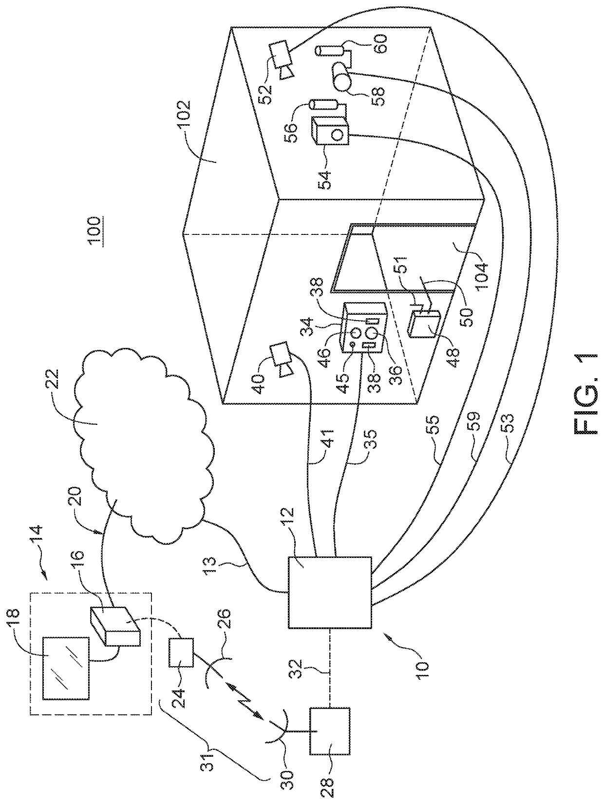
[0054]Referring to FIG. 1, one embodiment of a remote confined space monitoring system is shown. In some embodiments, monitoring system 10 can comprise of control panel 12 located at work site 100 comprising confined work space 102. ...


PUM


Abstract

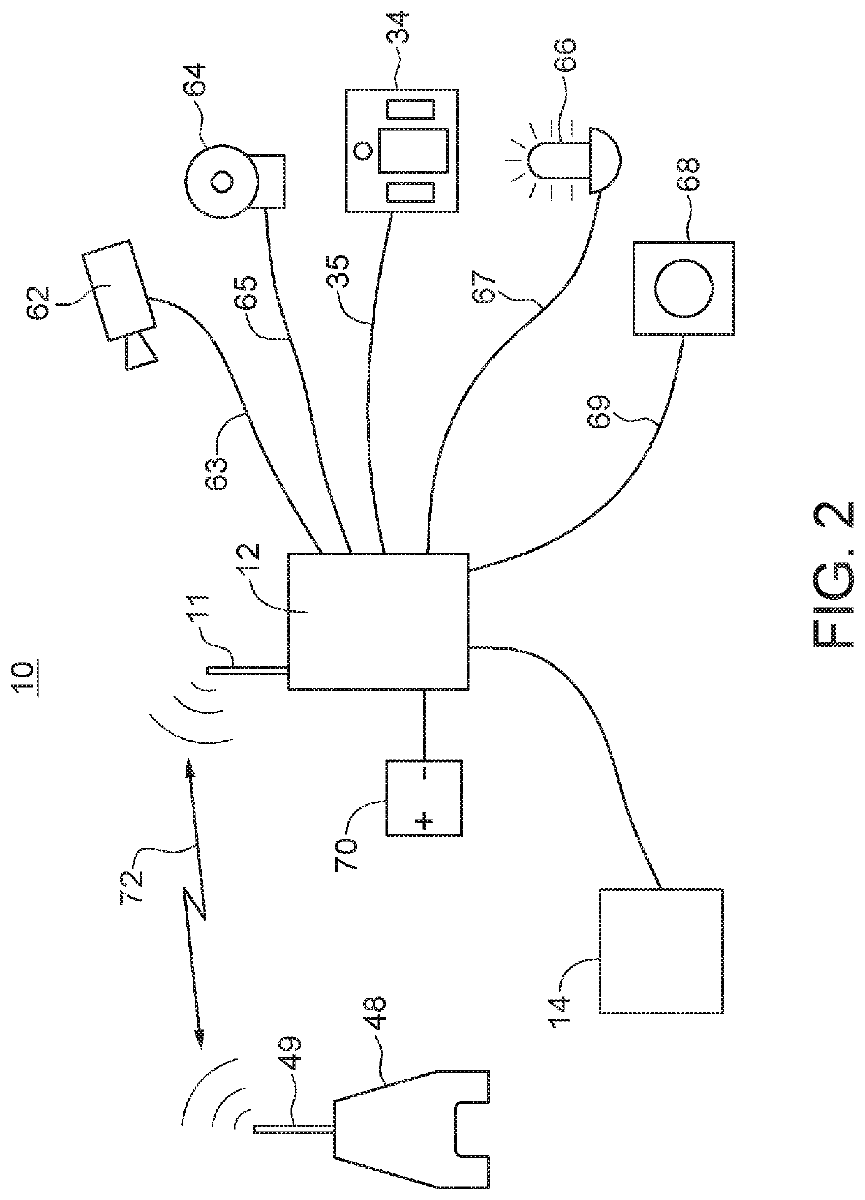
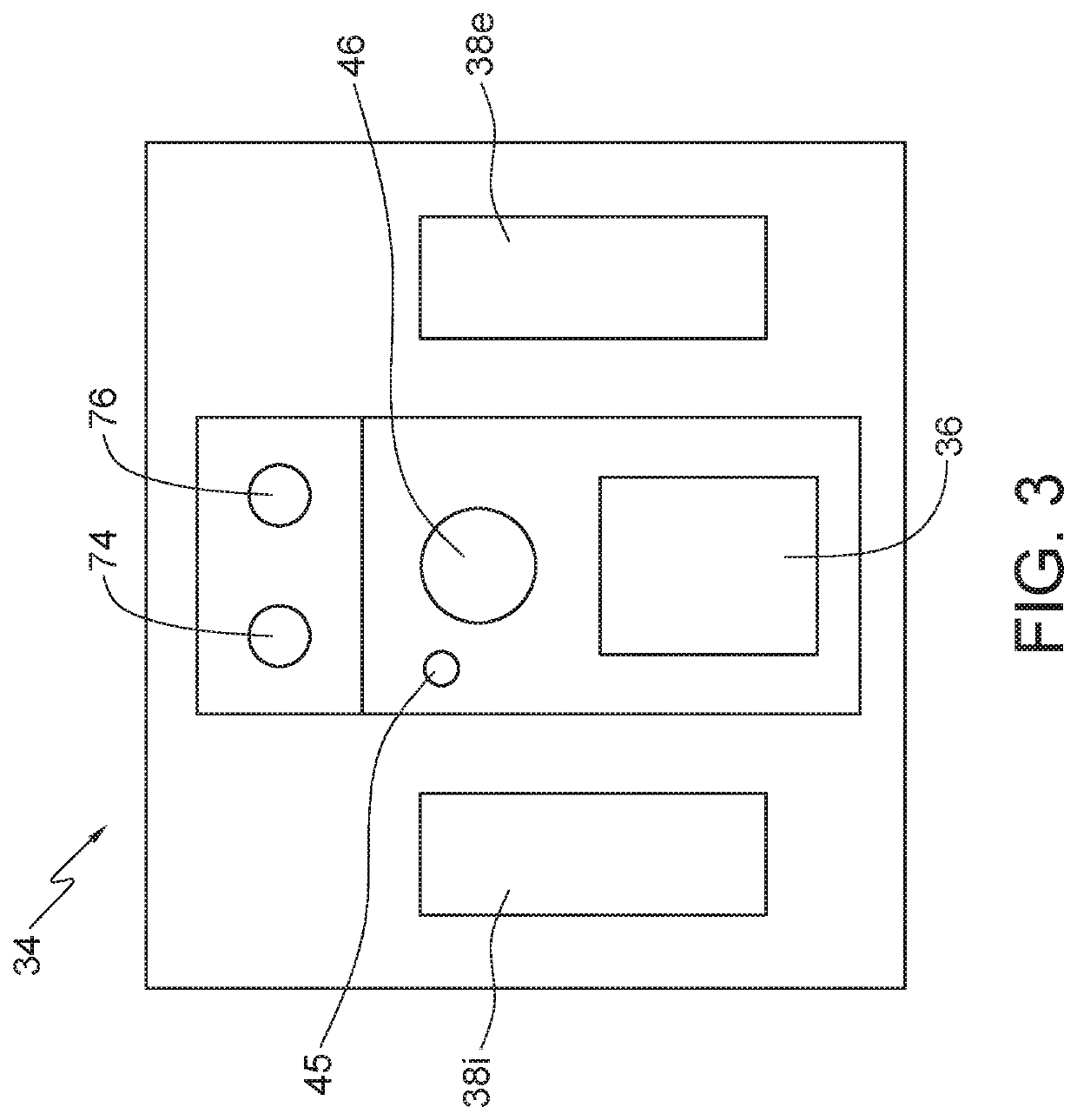
A system and method for remotely monitoring confined work spaces. The system can have subcomponents including a badging station for recording ingress and egress in and out of the work space, intercom systems for inside and outside of the work space, alarm systems inside and outside of the work space, cameras located inside and outside of the work space, and a gas detector for detecting gases in the work space. The subcomponents can be connected to a control panel that can relay data and communications to and from the subcomponents to a central dispatch center.

Description

PRIORITY STATEMENT & CROSS-REFERENCE TO RELATED APPLICATIONS[0001]This application claims priority from U.S. Patent Application Ser. No. 62 / 810,746 entitled “Remote Confined Work Space Monitoring System and Method” and filed on Feb. 26, 2019, which is hereby incorporated by reference, in entirety, for all purposes.TECHNICAL FIELD OF THE INVENTION[0002]The present disclosure is related to the field of remotely monitoring work activity in confined work spaces.BACKGROUND OF THE INVENTION[0003]For the purposes of this description and the claims that follow, the term “confined work space” shall be defined as:[0004]a) is large enough for personnel to enter fully and perform assigned work;[0005]b) is not designed for continuous occupancy by personnel; and[0006]c) has a limited or restricted means of entry or exit.[0007]Confined work spaces can include underground vaults, tanks, storage bins, pits, diked areas, vessels, silos or other similar areas. By definition, a permit-required confined...

Claims


Application Information

Patent Timeline
IPC IPC(8): G08B21/16H04M11/02H04N7/14G08B5/38G08B29/18G07C9/29
CPCG08B29/181H04M11/025H04N7/147G08B5/38G07C9/29G08B21/16G08B7/06G08B13/19632G08B21/12G07C9/27G07C9/28H04N7/181
Inventor LAROCQUE, DARREN DEANCHONKOLAY, CAREY SHAWNPAREDES, ROBERTO ALEJANDROHAMILTON, DAVID JOHN
Owner IMPACT SAFETY SOLUTIONS LTD
Learn More