Manufacture of fixed tip catheters

a technology of fixed tip and catheter, which is applied in the field of catheters, can solve the problems of reducing efficiency, reducing dialysis efficiency, and prolonging the duration of treatment needed for adequate dialysis

Inactive Publication Date: 2009-08-20
BARD ACCESS SYST
View PDF100 Cites 43 Cited by
  • Summary
  • Abstract
  • Description
  • Claims
  • Application Information

AI Technical Summary

Benefits of technology

[0020]In still another aspect of the invention, a method of forming a fixed tip catheter is disclosed including the steps of: splitting a distal end of a catheter body having two or more lumens at a septum dividing two of the lumens to isolate a first distal end lumen tube, truncating the catheter body such that the first distal end lumen tube is

Problems solved by technology

However, conditions such as access recirculation decrease efficiency.
Excess recirculation effectively reduces dialysis efficiency and lengthens the duration of the treatment needed for adequate dialysis.
Access recirculation can be particularly of concern when using a double lumen catheter due to the close proximity of the intake and outflow ports at the distal tip of the cat

Method used


Image

  • Manufacture of fixed tip catheters
  • Manufacture of fixed tip catheters
  • Manufacture of fixed tip catheters

Examples


Embodiment Construction

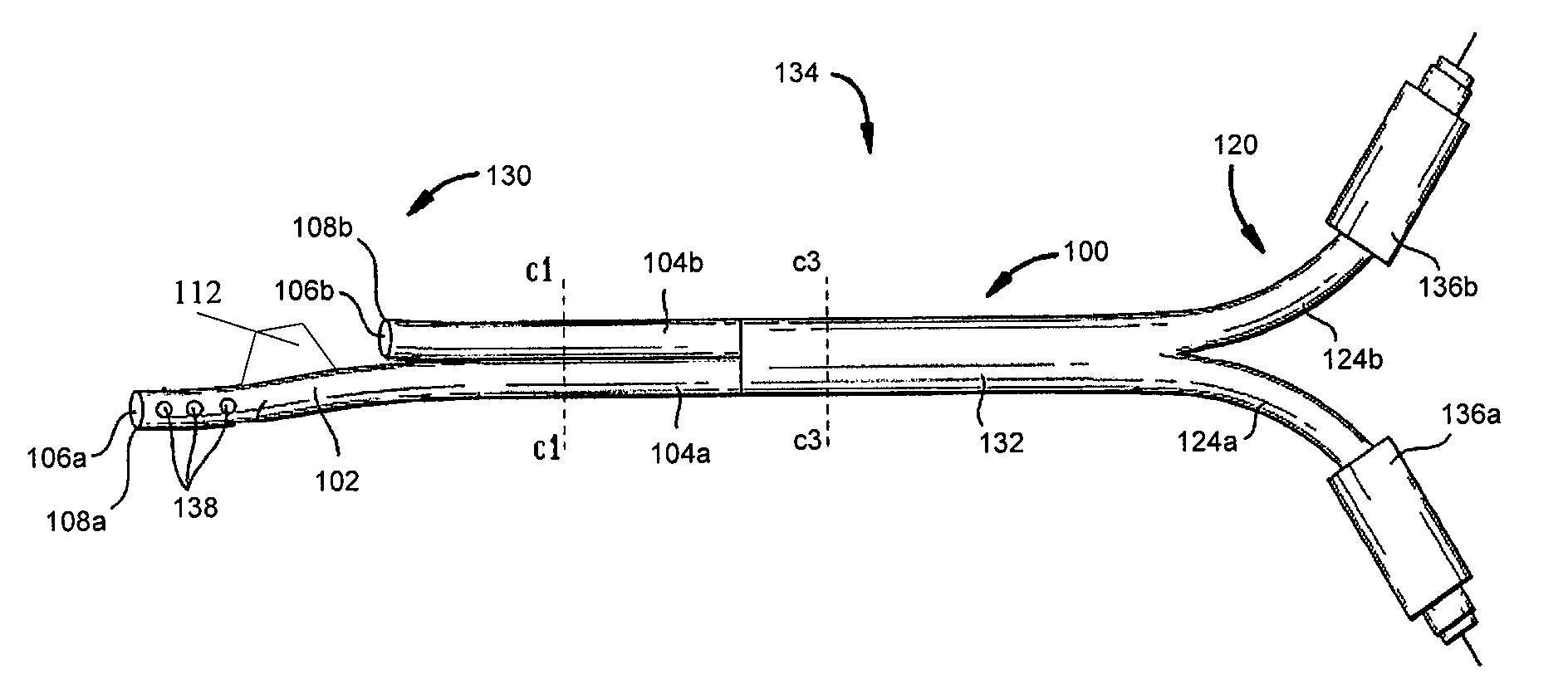
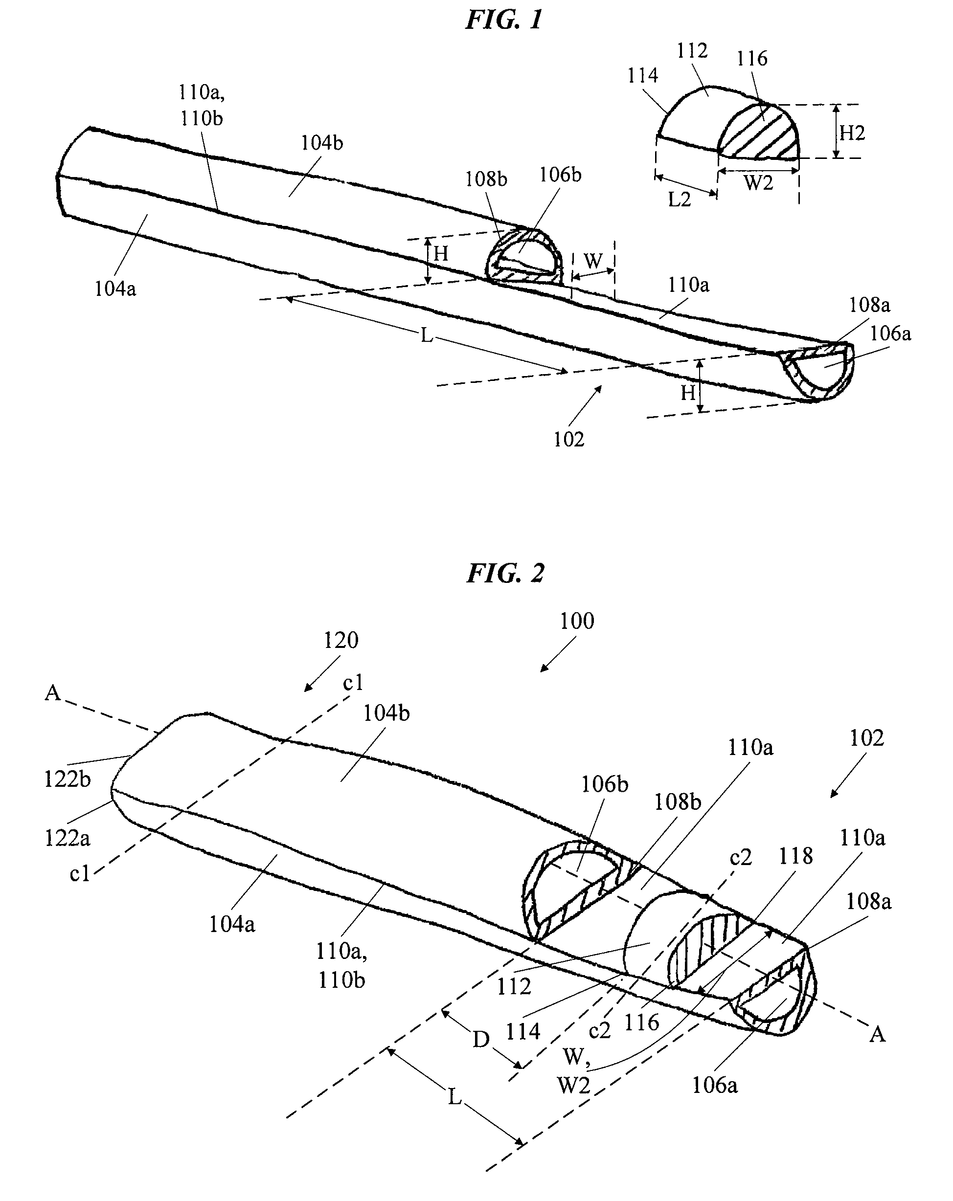
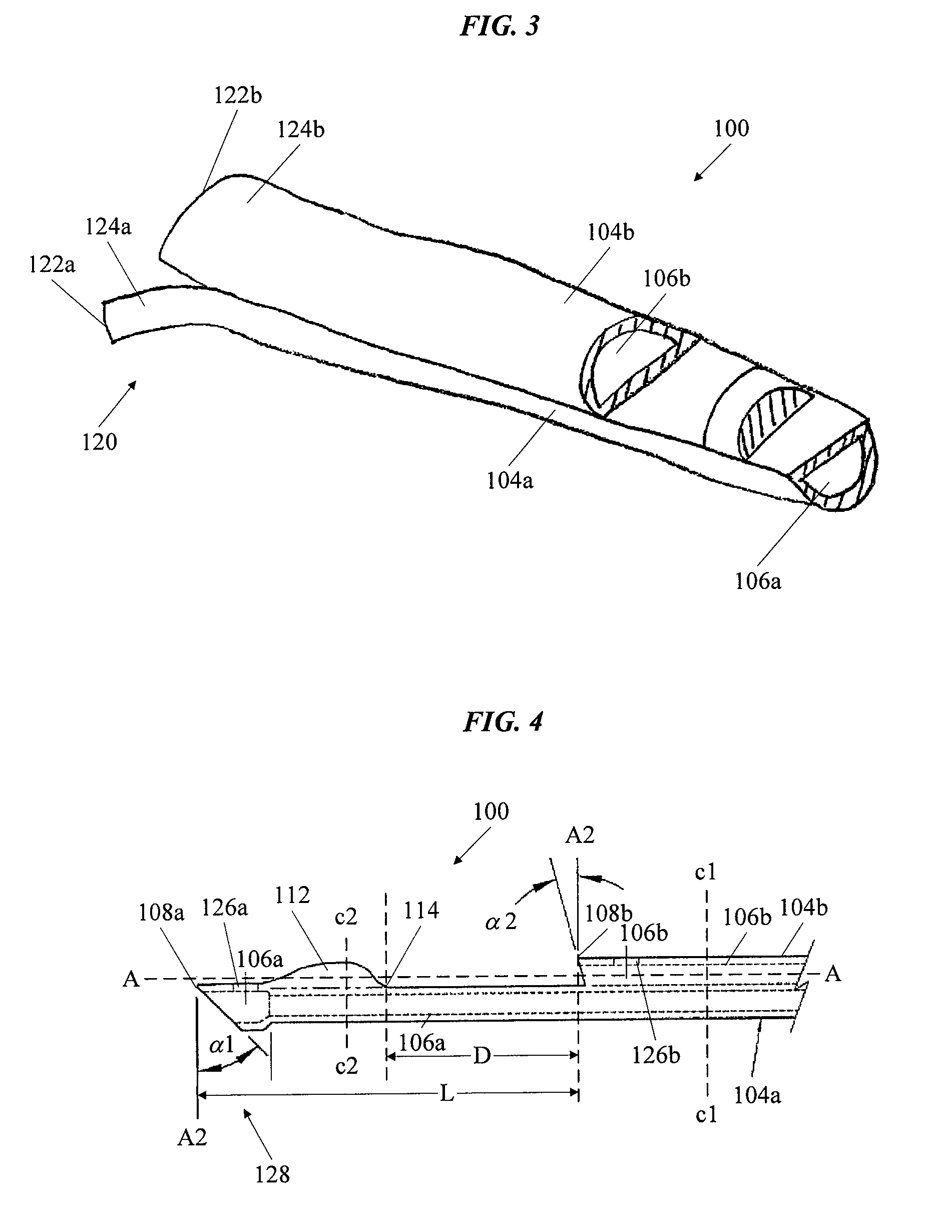
[0068]FIG. 1 shows first and second catheter tubes or bodies 104a, 104b (collectively, the tubes or bodies 104) and a flow diverting structure 112 in an initial, unattached configuration (e.g., prior to the diverting structure's attachment to one of the tubes 104). The tubes 104 include respective inner lumen pathways 106a, 106b (collectively, the pathways 106) extending longitudinally through the tubes 104 for, e.g., the extraction or return of blood or other bodily fluids. The first tube 104a (also referred to as “the longer tube 104a”) includes a distal tip portion 102 having a distal end 108a that extends a longitudinal length L beyond a distal end 108b of the second tube 104b (also referred to as “the shorter tube 104b”). The distal ends 108a, 108b (collectively, the distal ends 108) of the lumens 104 can be open to provide fluid passageways through the pathways 106, e.g., for blood removal and return. Each of the tubes 104 in this illustrated embodiment has a substantially D-s...


PUM

PropertyMeasurementUnit
Fractionaaaaaaaaaa
Lengthaaaaaaaaaa
Flow rateaaaaaaaaaa

Abstract

Methods of forming catheters are disclosed, together with methods of forming fixed tip catheters. In one aspect of the invention, the manufacturing methods can include the steps of: providing first and second catheter tubes, a distal end of the first catheter tube extending a longitudinal length beyond a distal end of the second catheter tube, and attaching a flow diverting structure to an outside surface of the first catheter tube between the distal ends of the first and second catheter tubes. The flow diverting structure can be oriented on the first catheter tube to divert fluid flowing through an inner lumen of the second catheter tube.

Description

CROSS REFERENCE TO RELATED APPLICATIONS[0001]The present application claims the priority of U.S. Provisional Application Ser. No. 61 / 029,051 filed Feb. 15, 2008 entitled “Manufacture of Fixed Tip Catheters,” which is herein incorporated by reference in its entirety. This application is also related to commonly owned U.S. patent application Ser. No. ______ filed concurrently herewith entitled “Catheters With Enlarged Arterial Lumens” (Attorney Docket No. 101430-238), U.S. patent application Ser. No. ______ filed concurrently herewith entitled “Fusion Manufacture of Multi-Lumen Catheters” (Attorney Docket No. 101430-236), and U.S. patent application Ser. No. ______ filed concurrently herewith entitled “Manufacture of Split Tip Catheters” (Attorney Docket No. 101430-234), each of which are herein incorporated by reference in their entireties.BACKGROUND[0002]The present invention generally relates to catheters and preferably to multi-lumen catheters used for vascular access.[0003]Multi-...

Claims


Application Information

Patent Timeline
IPC IPC(8): B23P19/04B23P11/00
CPCA61M25/001A61M25/003A61M25/0032Y10T29/49826A61M2025/0034A61M2025/0037Y10T29/49888A61M2025/0031
Inventor NIMKAR, SHEKHAR D.TOBIN, ERIC
Owner BARD ACCESS SYST
Why Eureka
Try Eureka