Auto-calibrating test sensors

a technology of auto-calibrating and test sensors, which is applied in the field of test sensors, can solve the problems of high cost of manufacturing millions of sensor packages, each having a calibration circuit or label to assist in calibrating the sensor package,

Inactive Publication Date: 2009-08-20
BAYER HEALTHCARE LLC
View PDF99 Cites 27 Cited by
  • Summary
  • Abstract
  • Description
  • Claims
  • Application Information

AI Technical Summary

Benefits of technology

[0015]According to another process, a method of using a test sensor and a meter is disclosed. The test sensor and meter use calibration information in determining information related to an analyte in a fluid sample. The method comprises the act of providing a test sensor including a base having a first end and a second opposing end. The test sensor further includes a fluid-receiving area configured to receive the fluid sample. The test sensor further includes at least one notch formed therein. The method further comprises the act of assigning calibration information to the test sensor. The method further comprises the act of providing a meter with a test-sensor opening. The meter includes a piezoelectric element positioned at or near the test-sensor opening. The piezoelectric element receives the at least one notch. The method further comprises the act of placing the test sensor into the test-sensor opening of the meter. The method further comprises the act of moving the test sensor so as to compress the piezoelectric element a distance. The method further comprises the act of determining a measured voltage of the piezoelectric element. The measured voltage corresponds to the distance that the piezoelectric element is compressed. The method further comprises the act of applying the calibration information using the measured voltage to assist in determining the information related to the analyte in the fluid sample.

Problems solved by technology

Manufacturing millions of sensor packages, each having a calibration circuit or label to assist in calibrating the sensor package, can be expensive.

Method used


Image

  • Auto-calibrating test sensors
  • Auto-calibrating test sensors
  • Auto-calibrating test sensors

Examples


Embodiment Construction

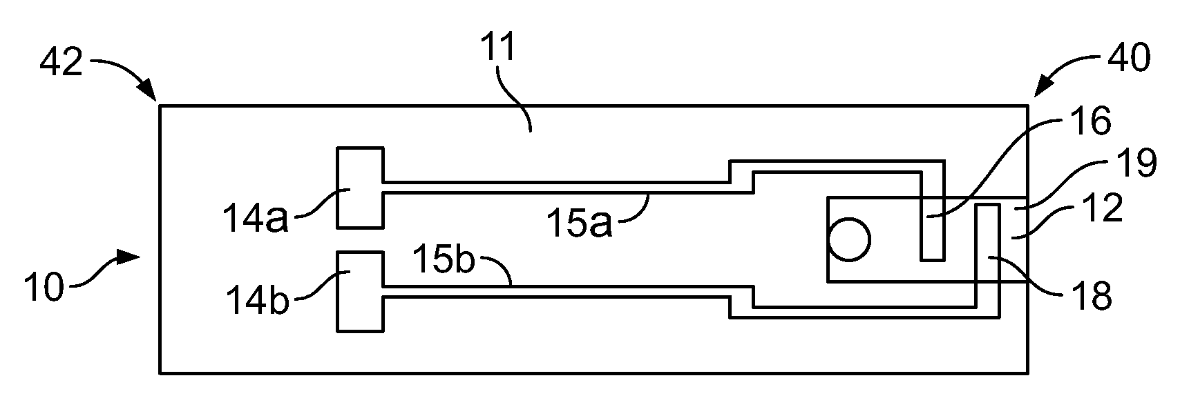
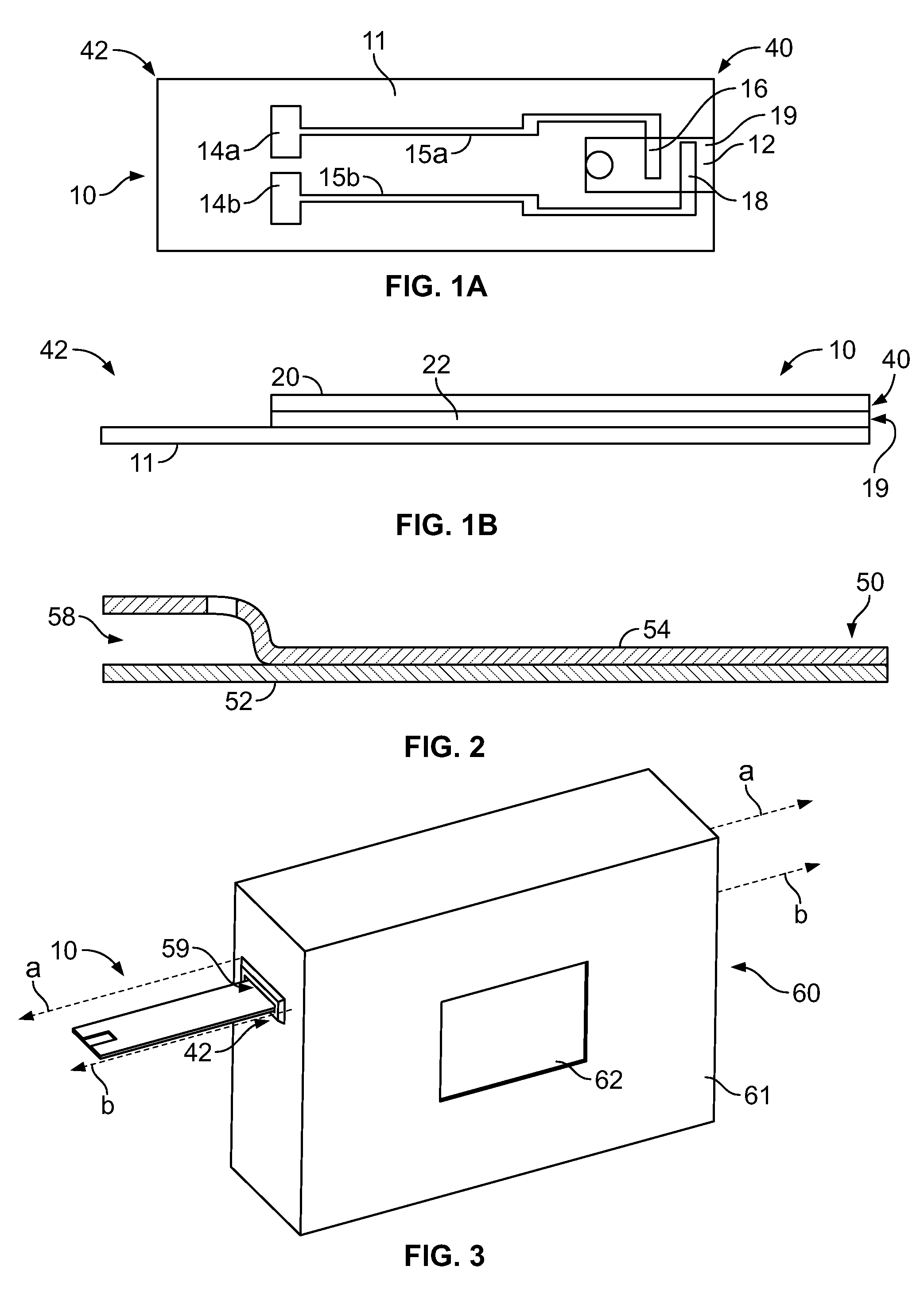
[0032]Generally, an instrument or meter uses a test sensor adapted to receive a fluid sample to be analyzed and a processor adapted to perform a predefined test sequence for measuring a predefined parameter value. A memory is coupled to the processor for storing predefined parameter data values. Calibration information associated with the test sensor may be read by the processor before or after the fluid sample to be measured is received, but not after the analyte concentration has been determined. Calibration information is generally used to compensate for different characteristics of test sensors, which will vary on a batch-to-batch basis.

[0033]The calibration information may be, for example, the lot specific reagent calibration information for the test sensor. The calibration information may be in the form of a calibration code. Selected information associated with the test sensor (which may vary on a batch-to-batch basis) is tested to determine the calibration information to be ...


PUM

PropertyMeasurementUnit
depthaaaaaaaaaa
sizeaaaaaaaaaa
resistanceaaaaaaaaaa

Abstract

A method of making a test sensor configured to assist in determining information related to an analyte in a fluid sample is disclosed. The method comprises the act of providing a base having a first end and a second opposing end. The method further comprises the act of providing a fluid-receiving area configured to receive a fluid sample. The method further comprises the act of assigning calibration information to the test sensor. The method further comprises the act of forming at least one notch such that a depth of the notch corresponds to the calibration information.

Description

CROSS-REFERENCE TO RELATED APPLICATION[0001]This application claims the benefit of U.S. Provisional Patent Application No. 61 / 065,873, filed Feb. 15, 2008 entitled “Auto-Calibrating Test Sensors”, which is hereby incorporated by reference in its entirety.FIELD OF THE INVENTION[0002]The present invention relates generally to test sensors that are adapted to determine an analyte concentration. More specifically, the present invention generally relates to auto-calibrating test sensors.BACKGROUND OF THE INVENTION[0003]The quantitative determination of analytes in body fluids is of great importance in the diagnoses and maintenance of certain physiological abnormalities. For example, lactate, cholesterol, and bilirubin should be monitored in certain individuals. In particular, it is important that diabetic individuals frequently check the glucose level in their body fluids to regulate the glucose intake in their diets. The results of such tests may be used to determine what, if any, insul...

Claims


Application Information

Patent Timeline
Patent Type & Authority Applications(United States)
IPC IPC(8): G01N33/49G01R27/08
CPCG01N33/48771
Inventor SUN, HOI-CHEONG S.JOHNSON, GARY J.HOLZER, MATTHEWWU, MUCHEN, JUN
Owner BAYER HEALTHCARE LLC
Why Eureka
Try Eureka