Low differential pressure transducer

Active Publication Date: 2009-08-20
KULITE SEMICON PRODS
View PDF7 Cites 13 Cited by
  • Summary
  • Abstract
  • Description
  • Claims
  • Application Information

AI Technical Summary

Problems solved by technology

However, in prior art devices which utilize a force applied to two separate diaphragms, there is a problem in low pressure devices to bring out the leads.
This problem resulting in one of the diaphragms of the differential transducer being smaller than the other diaphragm.
Thus the prior art devices because of the problem in bringing out the leads as will be further explain

Method used


Image

  • Low differential pressure transducer
  • Low differential pressure transducer
  • Low differential pressure transducer

Examples


Example

DETAILED DESCRIPTION OF THE FIGURES

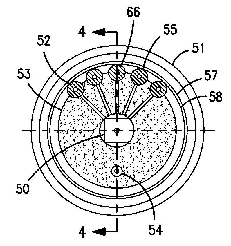
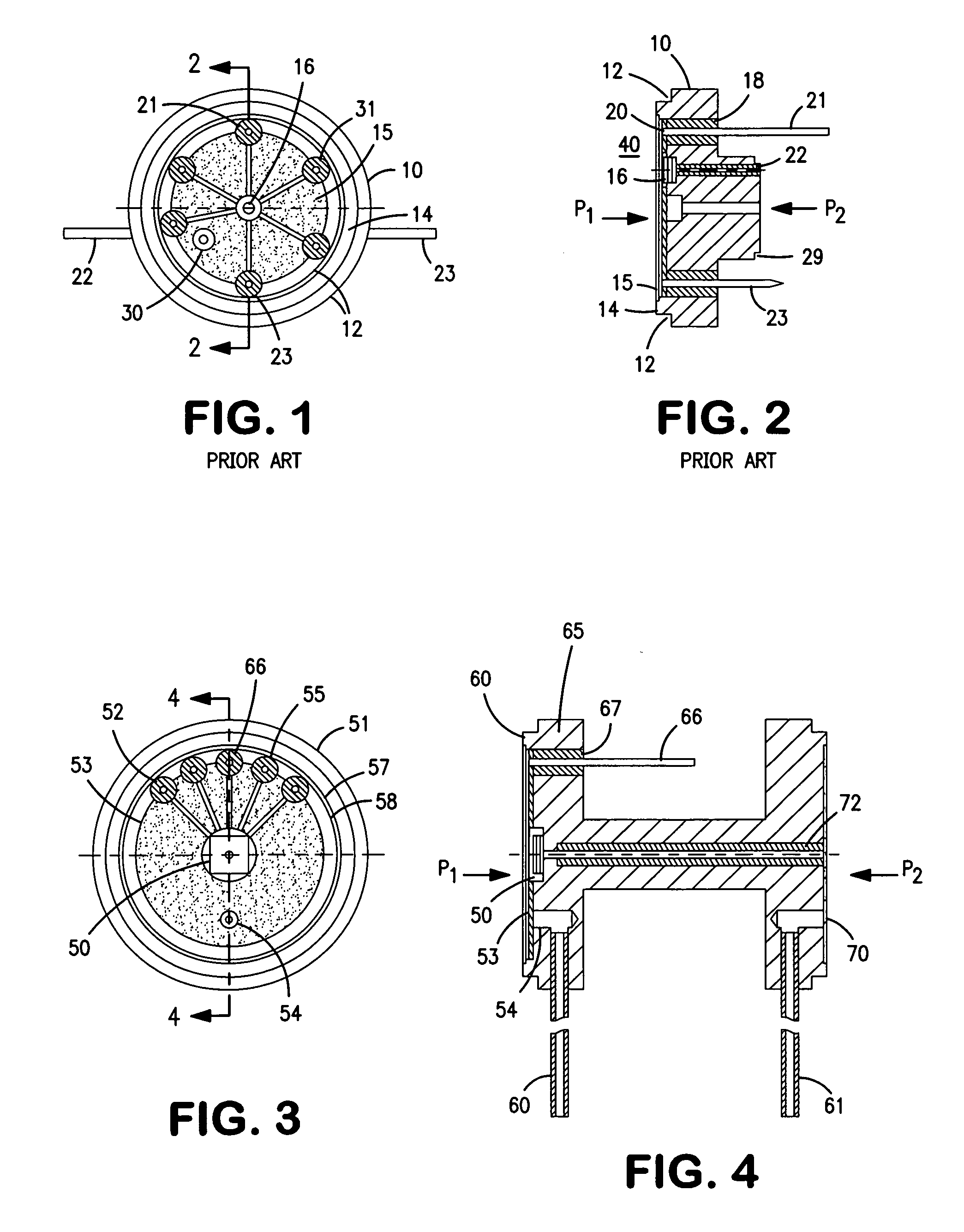
[0014]Referring to FIGS. 1 and 2 there is shown a prior art low pressure differential pressure transducer. Essentially, the pressure transducer basically consists of a metal housing 10 which has a outer peripheral indented flange 12 and a series of concentric rims or flanges as 14 and so on. The flanges are to accommodate an isolation diaphragm 15 which is shown in FIG. 2. The diaphragm is not shown in FIG. 1 in order to clarify the presentation. As seen in FIG. 1 there is a first and second oil fill tube as 22 and 23. Essentially the transducer 10 is a differential transducer and is seen in FIG. 2 has an isolation diaphragm in the front 20 and an isolation diaphragm in the back 29. The device operates such that when a pressure P1 is applied to the front of the diaphragm 20 while pressure P2 is applied to the back of the isolation diaphragm 29. The transducer has a sensor module 16. The module 16 is an oil filled unit having a piezoresistive Wheats...


PUM


Abstract

A pressure transducer has an H-shaped cross-sectional header having a front and a back section. The front and back sections are of equal diameter and are circular. Each front and back section has a depression with an isolation diaphragm covering the depression. Each diaphragm is of equal size and the depressions communicate one with the other via a central channel in the central arm of the H. A pressure sensor communicates with the channel, where the pressure sensor responds to a first pressure applied to the first isolation diaphragm and a second pressure applied to the second isolation diaphragm. The pressure sensor produces an output equal to the difference in pressure. The differential pressure transducer having both diaphragms of the same size and still enabling leads from the sensor to be brought out.

Description

[0001]This application is a continuation-in-part (CIP) of Ser. No. 12 / 070,255 filed on Feb. 14, 2008 under the same title.FIELD OF THE INVENTION[0002]This invention relates to pressure transducers and more particularly to a low differential pressure transducer and header.BACKGROUND OF THE INVENTION[0003]A differential pressure transducer is a device which provides an output which is the difference between two input pressures. For example, when a Pressure P1 is applied to one face of a deflecting diaphragm and a pressure P2 is applied to the other face of the deflecting diaphragm the resulting deflection will be determined by the difference in pressure (as for example P1-P2). There are other differential pressure transducers which essentially use two separate semiconductor structures each structure having its own diaphragm and the piezoresistor devices which are employed on the diaphragm surface are connected together to form a bridge which will provide a differential output. Referen...

Claims


Application Information

Patent Timeline
IPC IPC(8): G01L9/06
CPCG01L19/0645G01L13/025
Inventor KURTZ, ANTHONY D.
Owner KULITE SEMICON PRODS
Why Eureka
Try Eureka