Spin-stabilized lander

a spin-stabilized, lander technology, applied in the field of soft landing systems, can solve the problems of high system cost, simple additional liquid propellant needed, and the cost of roaming in this approach

Inactive Publication Date: 2009-08-20
ECLIPTIC ENTERPRISES CORP
View PDF2 Cites 50 Cited by
  • Summary
  • Abstract
  • Description
  • Claims
  • Application Information

AI Technical Summary

Benefits of technology

[0007]The invention provides a novel, low-cost, spin-stabilized lander architecture capable (with appropriate system scaling tailored to the attributes of the target) of performing a soft-landing on a solar-system body such as Earth's Moon, Mars, Venus, the moons of Mars,

Problems solved by technology

Such systems were very expensive.
The cost of roaming in this approach

Method used


Image

  • Spin-stabilized lander
  • Spin-stabilized lander
  • Spin-stabilized lander

Examples


Embodiment Construction

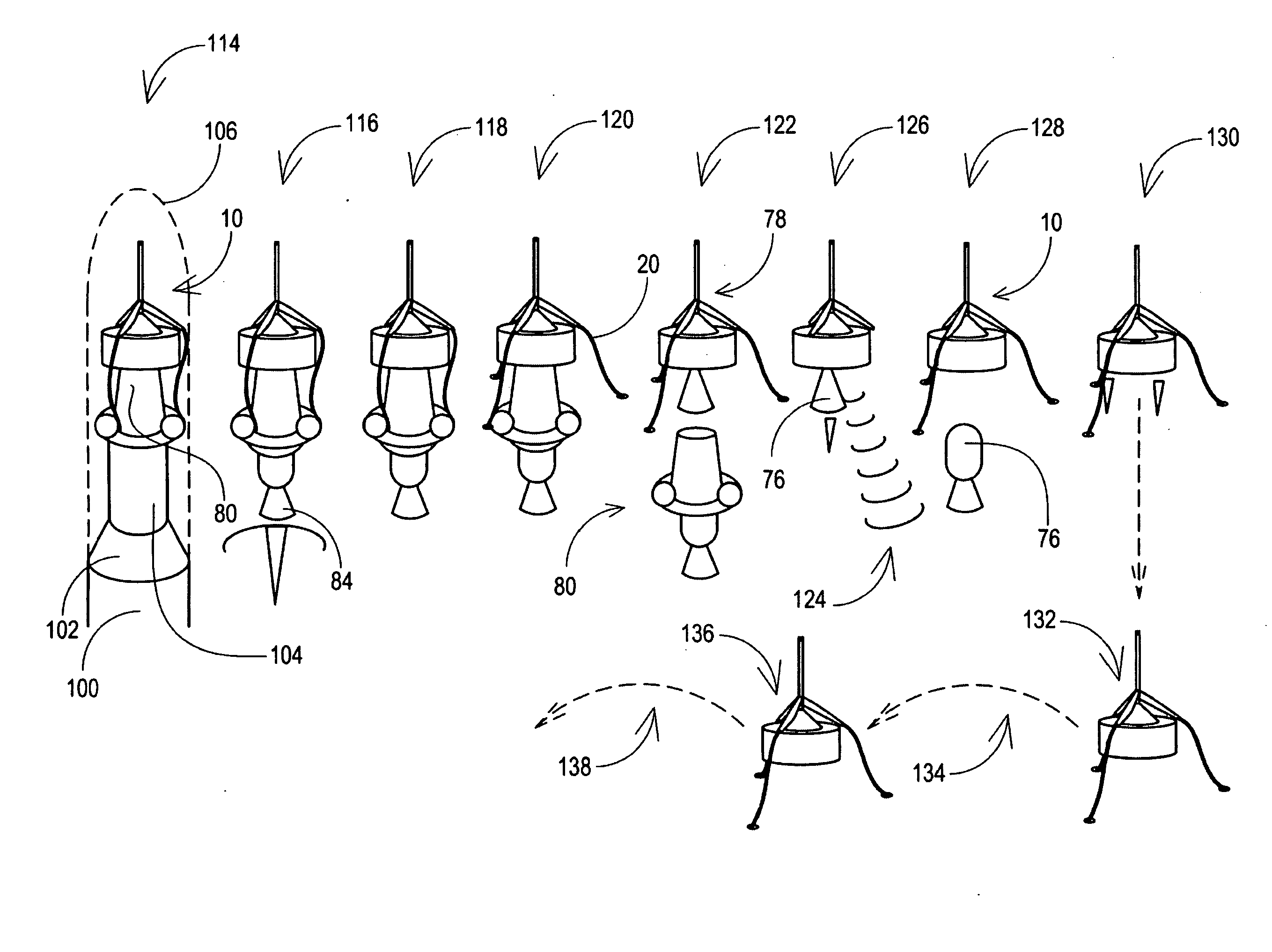
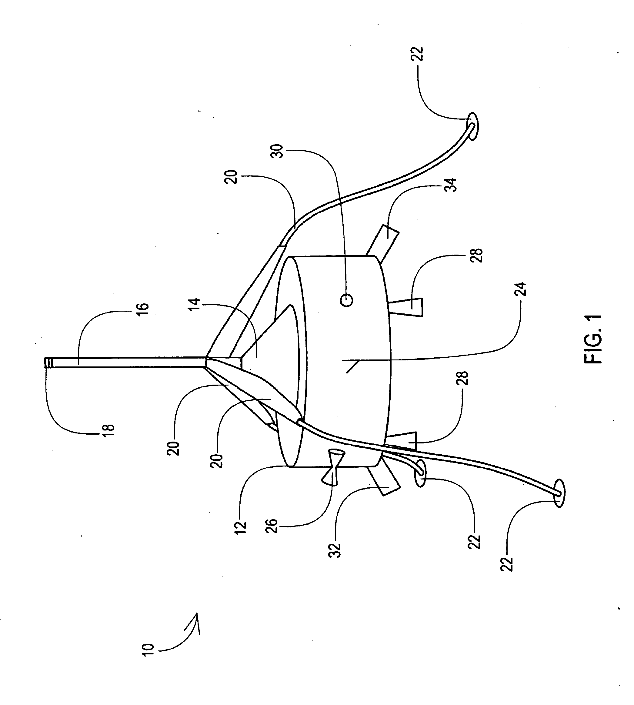
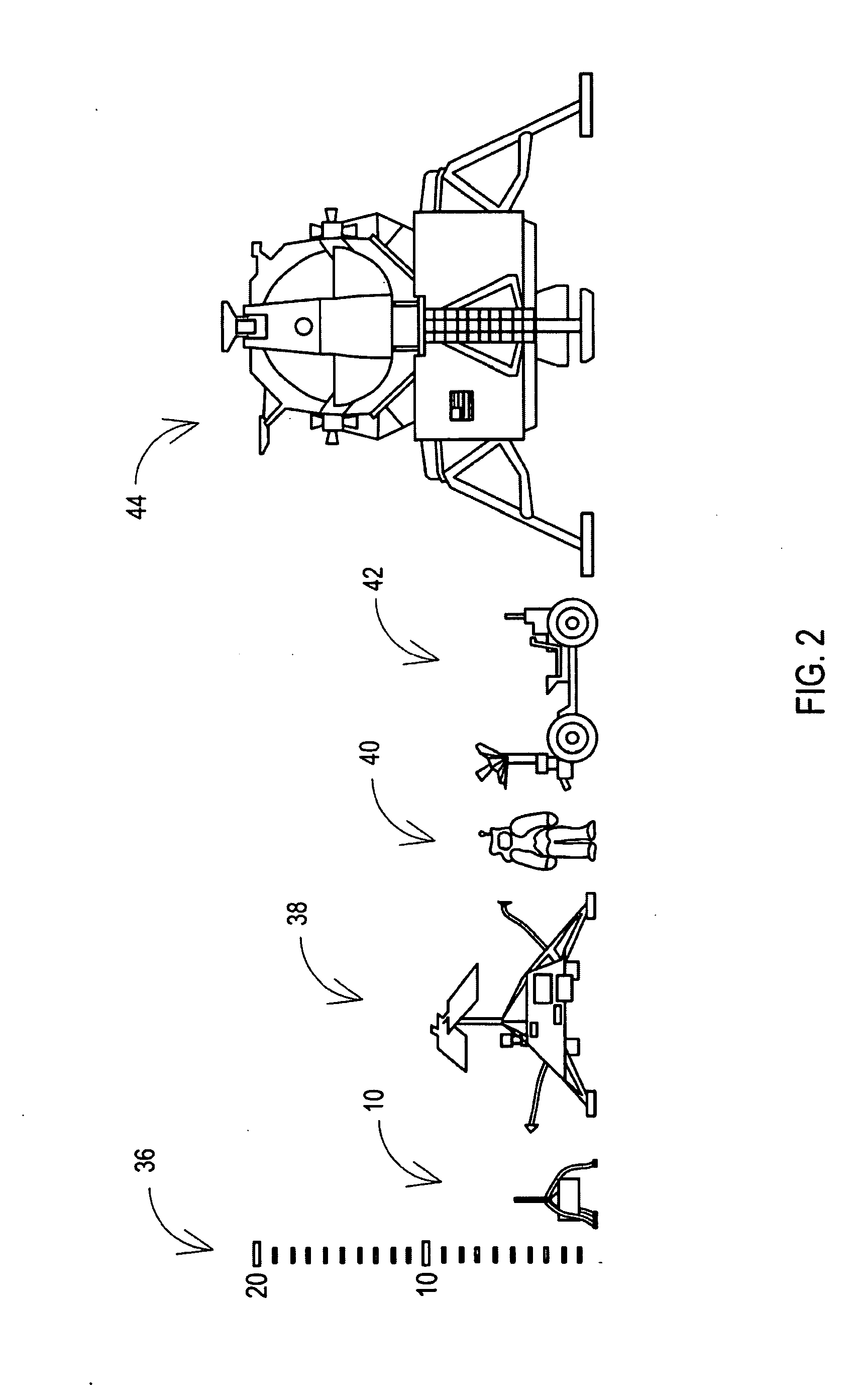
[0017]The present invention provides a novel, spin-stabilized vehicle for landing on, and moving about, a solar system body. Compared to conventional lander design approaches demonstrated during the past 45 years or so, the mass savings, overall packaging efficiency and multi-functional capabilities brought about by the present invention enable soft landers to be launched by existing and envisioned rockets on the lower end of the performance and cost scale. This landing approach, suitably modified for the particular mission, will permit low cost commercial and scientific missions to the Moon and other targets in the solar system.

[0018]The present invention solves this problem by using many design features of the 1960s spin-stabilized Syncom communication satellite, adding the functional elements needed for the transfer orbit to the Moon (or other solar-system body), landing and roaming on the lunar surface (or other body), and implementing the electronic elements in modern, mostly d...


PUM


Abstract

The invention provides a novel, low-cost, spin-stabilized lander architecture capable (with appropriate system scaling tailored to the attributes of the target) of performing a soft-landing on a solar-system body such as Earth's Moon, Mars, Venus, the moons of Mars, Jupiter, Saturn, Uranus and Neptune, selected near-Earth and main-belt asteroids, comets and Kuiper belt objects and even large human-made objects, and also moving about on the surface of the target solar-system body after the initial landing in movement akin to hopping.

Description

[0001]This application claims priority to co-pending U.S. provisional application Ser. No. 61 / 023,195 filed Jan. 24 2008.TECHNICAL FIELD[0002]The present invention applies generally to the field of systems for soft landing on solar-system bodies, and in particular to apparatus and methods for a vehicle or “lander” capable of performing such a soft-landing and also capable of extensive mobility or roaming capability after the initial landing.BACKGROUND OF THE INVENTION[0003]Early unmanned landers used to explore the Moon in the 1960s, e.g., the U.S.S.R. Luna series and the U.S. Surveyor series, employed complex three-axis, body-stabilized systems, complex attitude and orbit control systems, complex thermal control systems, complex instrumentation systems, and complex landing systems. Such systems were very expensive. An objective of the present invention is to provide the capabilities of landers such as these at much lower cost, while adding new capabilities or enhanced capabilities ...

Claims


Application Information

Patent Timeline
IPC IPC(8): B64G1/28B64G1/38B64G1/40B64G1/10G01S13/58H01Q1/28H01Q3/00
CPCB64G1/16B64G1/242B64G1/281B64G1/401B64G1/402B64G2001/1071B64G1/62B64G1/646B64G1/66B64G2001/1064B64G1/404B33Y80/00B64G1/1071B64G1/1064
Inventor ROSEN, HAROLD ALVIN
Owner ECLIPTIC ENTERPRISES CORP
Why Eureka
Try Eureka