Water-cooling fan with humidifying effect

Inactive Publication Date: 2009-08-20
TANG YI LIN
View PDF2 Cites 37 Cited by
  • Summary
  • Abstract
  • Description
  • Claims
  • Application Information

AI Technical Summary

Benefits of technology

[0007]A second object of this invention is to offer a water-cooling fan to enable i

Problems solved by technology

As for air conditioners with any capacity, although they can satisfactorily drop down temperature but they have a rather high hardware cost and consu

Method used


Image

  • Water-cooling fan with humidifying effect
  • Water-cooling fan with humidifying effect
  • Water-cooling fan with humidifying effect

Examples


Embodiment Construction

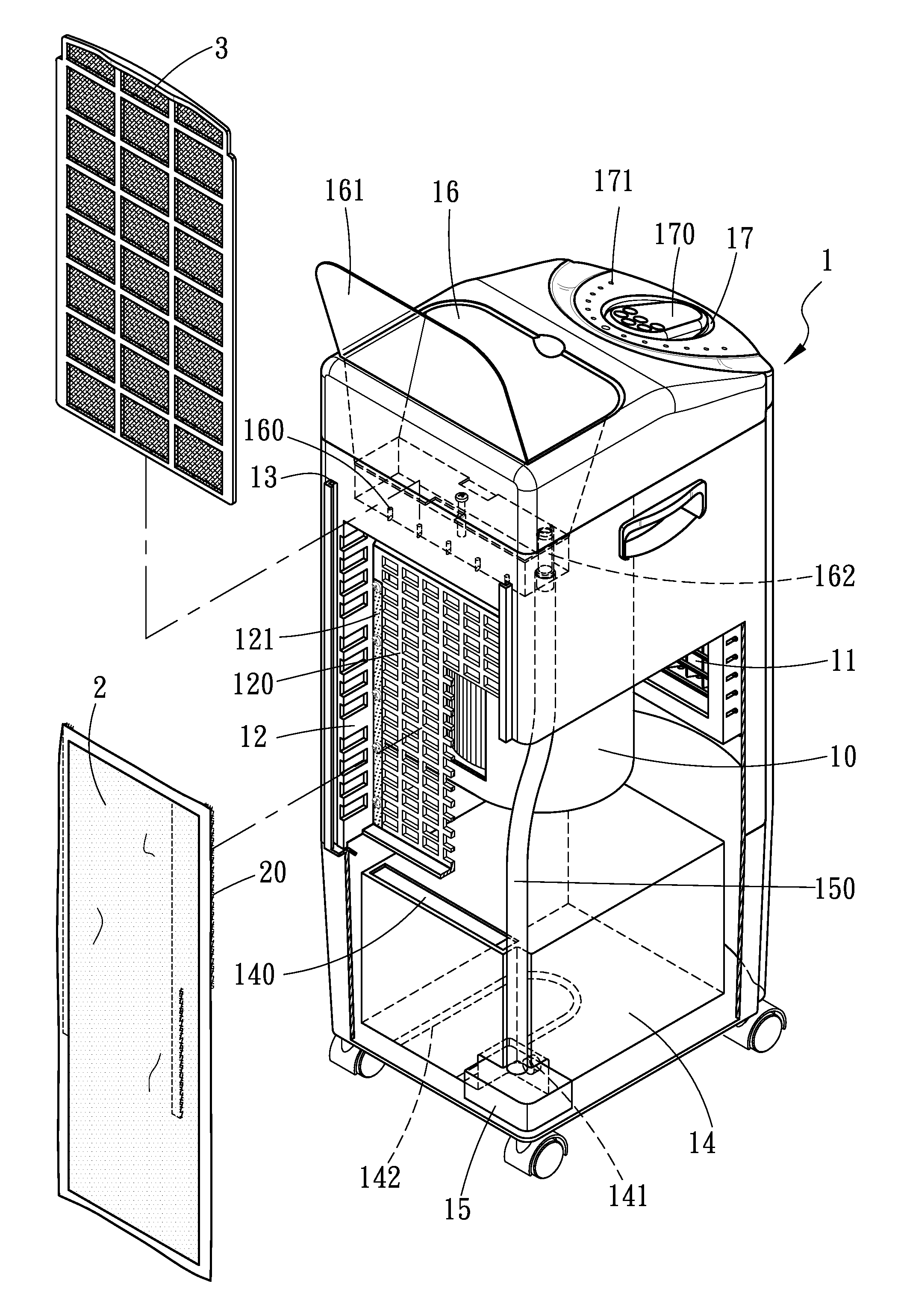
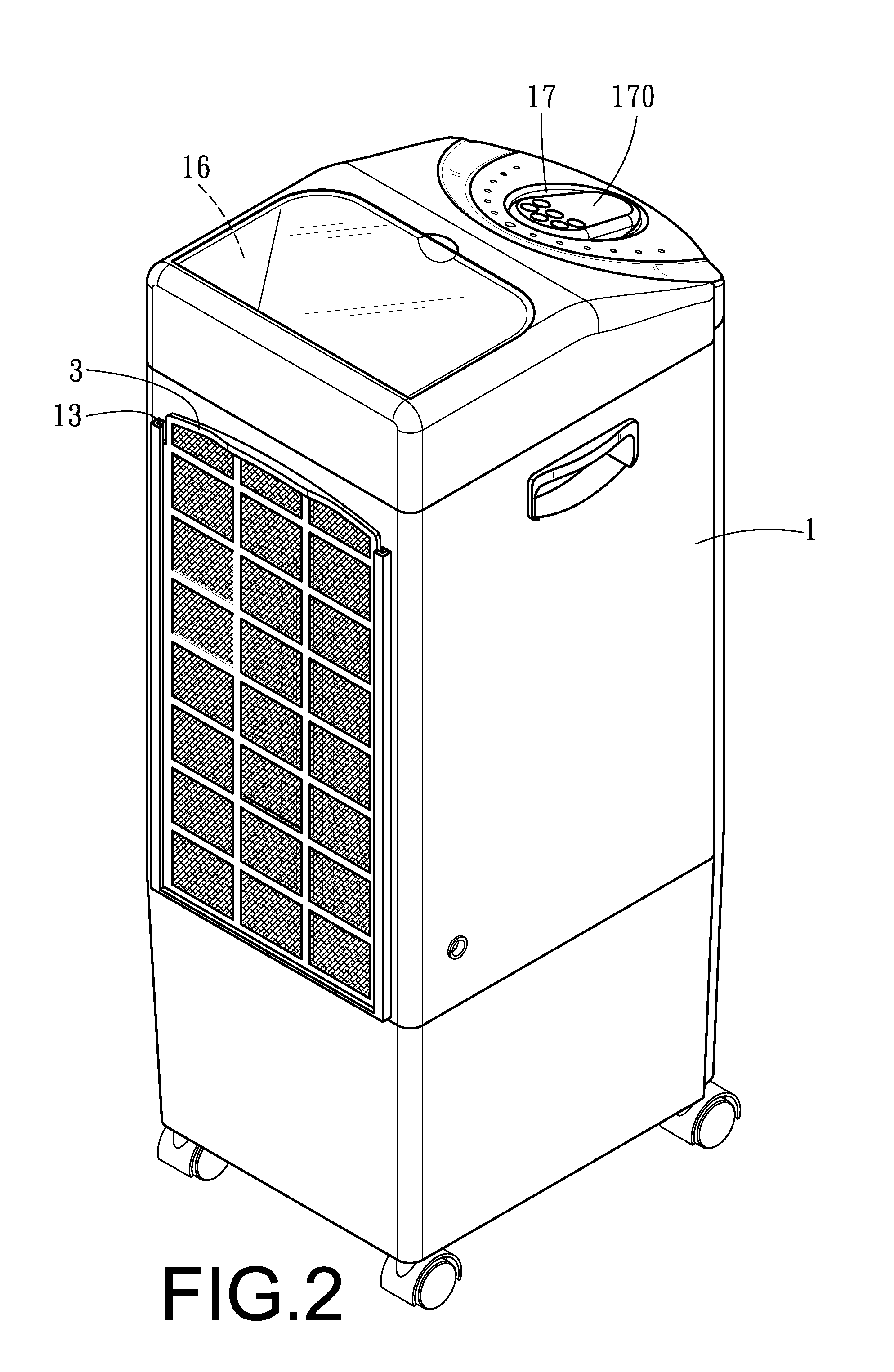
[0015]As shown in FIGS. 1˜3, a preferred embodiment of a water-cooling fan with humidifying effect in the present invention consists of a main body 1, a cloth curtain 2 and a filter 3.

[0016]The main body 1 is provided with a fan 10 installed therein, an air outlet 11 formed at a front side thereof, an air inlet 12 formed at a rear side thereof, a plugging groove 13 respectively positioned at two sides of the air inlet 12, a water tank 14 installed therein, a pump 15 installed therein, a sink 16 fixed at an upper portion thereof and a groove 17 fixed at a top thereof. The air inlet 12 is provided with a grating 120 disposed therein, and a Velcro band 121 attached around a circumference thereof. The water tank 14 made of materials resistant to high temperature is provided with a rectangular opening 140 bored at one side thereof, a water-exiting tube 141 located at a lower portion thereof for connecting with the pump 15, and at least one heater 142 fixed therein. The sink 16 is provide...


PUM

PropertyMeasurementUnit
Circumferenceaaaaaaaaaa
Humidityaaaaaaaaaa

Abstract

A water-cooling fan with humidifying effect includes a main body, a cloth curtain and a filter. The main body has a fan, an air outlet formed at its front, an air inlet formed at its rear, a plugging groove positioned respectively at two sides of the air inlet, a water tank, a pump and a sink. The circumference of the air inlet is attached with a Velcro band corresponding to a Velcro band fixed around the circumference of the cloth curtain. The water tank has an opening for the cloth curtain to extend into it, a water-exiting tube connected with the pump, and at least one heater fixed in its bottom. The sink has a plurality of water-dropping holes in its bottom and a water-entering tube for being connected with the pump. Such a fan can be used as a water-cooling fan or used to increase indoor humidity if necessary.

Description

BACKGROUND OF THE INVENTION[0001]1. Field of the Invention[0002]This invention relates to a water-cooling fan with humidifying effect, particularly to one able to cool down circulation air, make air circulated with an increased humidity if necessary, and have its cloth curtain and filter quickly disassembled for cleaning.[0003]2. Description of the Prior Art[0004]Commonly, in order to cool down hot indoor air with heat in summer or in a chamber, fans are used to quickly enhance air circulation to make people feel a little better, or air conditioners are employed to directly cool down temperature. Although conventional fans can speed air circulation but temperature is not lowered. As for air conditioners with any capacity, although they can satisfactorily drop down temperature but they have a rather high hardware cost and consume too much energy in comparison with conventional fans. Moreover, the heat exhausted is one of the factors making climate warming up.[0005]And, during the aut...

Claims


Application Information

Patent Timeline
IPC IPC(8): F24F5/00B01F3/04
CPCF24F6/04
Inventor LEE, MING-TSUNG
Owner TANG YI LIN
Why Eureka
Try Eureka