Primary part and linear electrical machine with force ripple compensation

a linear electrical machine and primary part technology, applied in the direction of dynamo-electric machines, synchronous machines, electrical apparatus, etc., can solve the problems of machining process rough running and drag errors, and achieve the effect of reducing electromagnetic asymmetries, improving drive characteristics, and improving accuracy of pole position identification

Inactive Publication Date: 2009-08-20
SIEMENS AG
View PDF3 Cites 11 Cited by
  • Summary
  • Abstract
  • Description
  • Claims
  • Application Information

AI Technical Summary

Benefits of technology

[0014]The use of the flux-guiding elements makes it possible to reduce the cogging force, i.e., the active and, in particular, the passive force ripple. At the end of the primary part, the voltages induced in the teeth to which windings are fitted are increased by the flux-guiding elements, ensuring that the EMF of the winding of the primary part is as uniform as possible.
[0041]Thus, in accordance with the invention, a linear electrical machine is provided that has reduced active and passive force ripple, i.e., cogging force.

Problems solved by technology

This results in vibration, rough running and drag errors during machining processes.

Method used


Image

  • Primary part and linear electrical machine with force ripple compensation
  • Primary part and linear electrical machine with force ripple compensation
  • Primary part and linear electrical machine with force ripple compensation

Examples


first embodiment

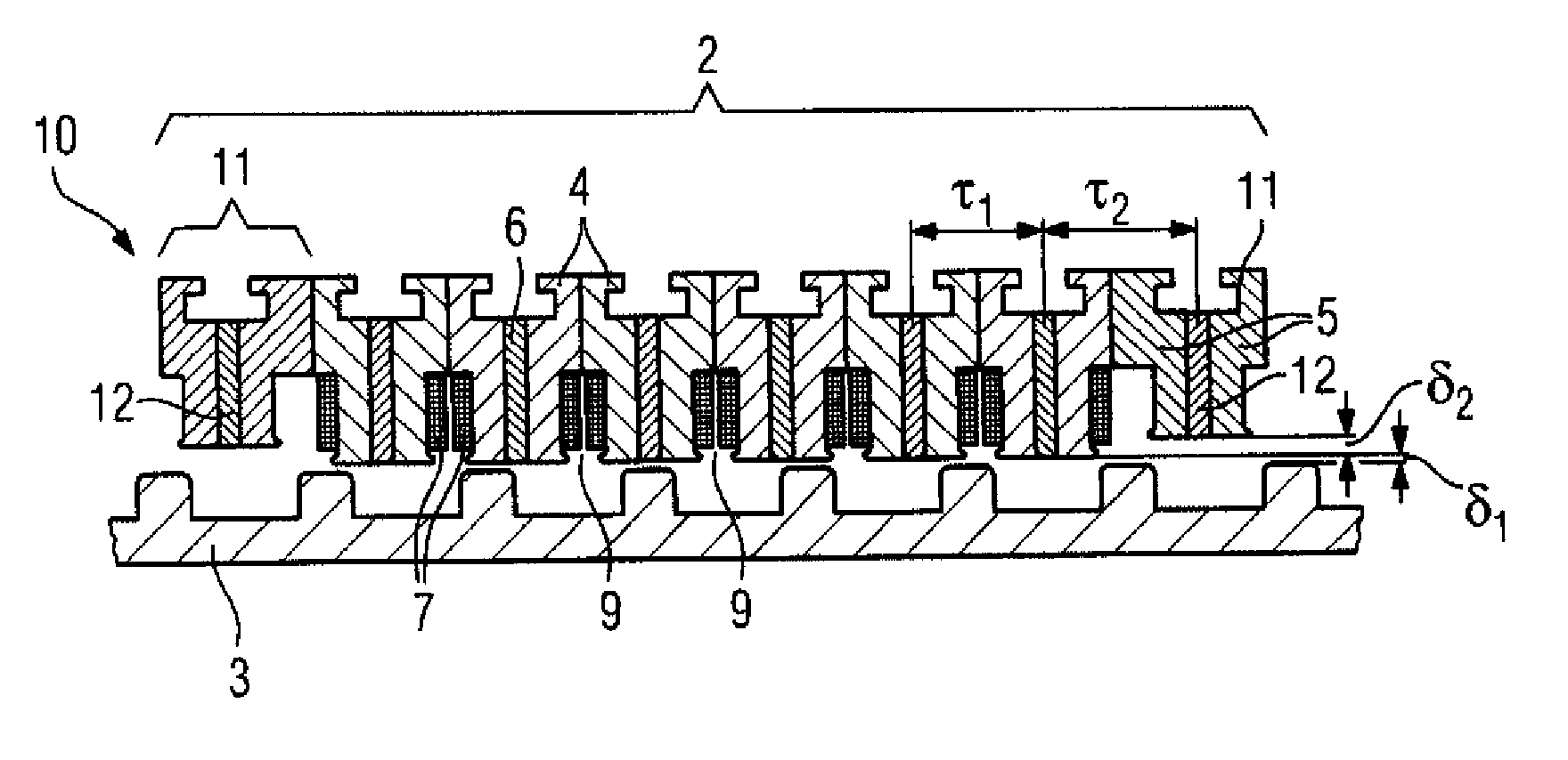
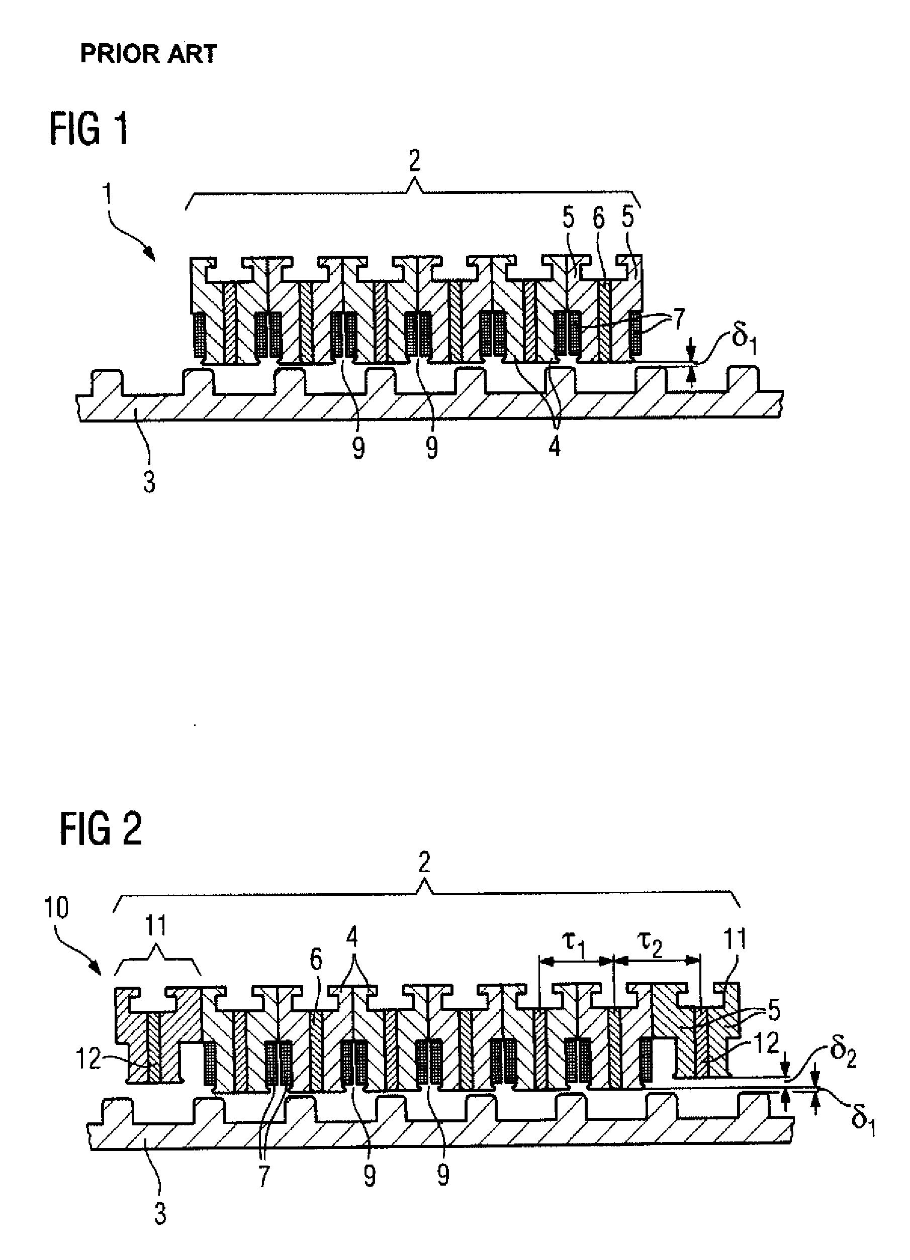
[0052]Referring now to FIG. 2, there is shown a schematic diagram of a linear electrical machine according to the invention, generally designated by reference numeral 10. Parts corresponding with those in FIG. 1 are denoted by identical reference numerals and not explained again. As shown in FIG. 2, in addition to the six tooth modules 4, the primary part 2 has additional two end-tooth modules 11, wherein one end-tooth module 11 is arranged on each end face of the primary part 2.

[0053]Each end-tooth module 11 is separated from the secondary part 3 by a second air gap δ2 in addition to the first air gap δ1, thus resulting in a larger air gap δ1+δ2 between the secondary part 3 and the end-tooth module 11 than between the rest of the primary part 2 and the secondary part 3.

[0054]Because of the larger air gap δ1+δ2 between the end-tooth module 11 and the secondary part 3, the permanent magnet 12 of the end-tooth module 11 is correspondingly smaller, that is to say shorter. The end-tooth...

second embodiment

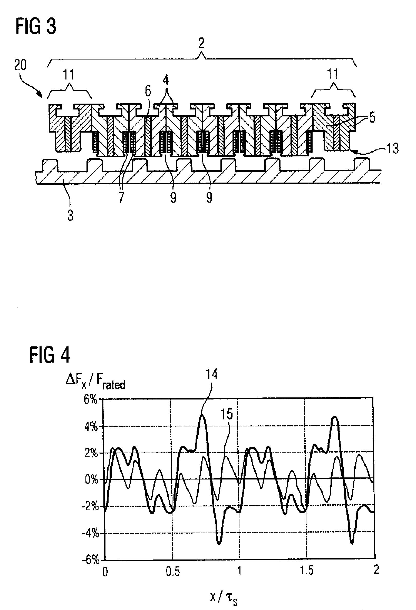
[0056]FIG. 3 shows the invention, another linear electrical machine 20. The primary part 2 has the additional two end-tooth modules 11 in addition to the six tooth modules 4, wherein one end-tooth module 11 is arranged on each end face of the primary part 2.

[0057]The linear electrical machine 20 corresponds essentially to the embodiment shown in FIG. 2, but each end-tooth module 11 has a slightly modified geometry. In particular, the end-tooth modules 11 have rounded corners 13.

[0058]FIG. 4 shows a graph that illustrates different cogging-force profile of two different electrical machines. The reference symbol 14 denotes the amplitude of the cogging force of the electrical machine 1 shown in FIG. 1, i.e., a machine without flux-guiding elements for reducing the force ripple. In contrast, reference numeral 15 denotes the amplitude of the cogging force of the electrical machine 10 shown in FIG. 2 that has end-tooth modules 11. FIG. 4 shows well that only minor cogging forces occur whe...


PUM


Abstract

A linear electric motor including a primary part having a flux guiding element on the end faces of the primary part, a three-phase winding on the primary part that produces a first magnetic field and a permanent magnet on each end face that produces a second magnetic field that is superimposed on the first field to reduce force ripple is disclosed. The primary part has tooth modules and also end-tooth modules. The end-tooth modules have no winding, are located on the end face, and are smaller in volume than and shaped differently from the tooth modules. The primary part is separated from a secondary part by an air gap, and the end-tooth modules are separated from the secondary part by an additional air gap.

Description

CROSS-REFERENCES TO RELATED APPLICATIONS[0001]This application claims the priority of European Patent Application, Serial No. 08002961, filed Feb. 18, 2008, pursuant to 35 U.S.C. 119(a)-(d), the content of which is incorporated herein by reference in its entirety as if fully set forth herein.BACKGROUND OF THE INVENTION[0002]The present invention relates to a primary part of a linear electrical machine, and to a linear electrical machine with a primary part.[0003]The following discussion of related art is provided to assist the reader in understanding the advantages of the invention, and is not to be construed as an admission that this related art is prior art to this invention.[0004]Linear electrical machines have a primary part and a secondary part. The primary part and the second part are opposite one another and are separated from one another by an air gap. The primary part is designed for electric current to be passed through it.[0005]It is possible for both the primary part and...

Claims


Application Information

Patent Timeline
Patent Type & Authority Applications(United States)
IPC IPC(8): H02K41/03
CPCH02K21/04H02K2213/03H02K41/033H02K21/44
Inventor JAJTIC, ZELJKOMATSCHEKO, GERHARDVOLMERT, CHRISTIAN
Owner SIEMENS AG
Why Eureka
Try Eureka