Probe device having a light source thereon

a technology of probe device and light source, which is applied in the direction of measurement device, electrical testing, instruments, etc., can solve the problems of increasing difficulty, increasing the physical dimensions of dut components, and becoming almost impossible for users to see well enough

Inactive Publication Date: 2009-08-20
AGILENT TECH INC
View PDF8 Cites 18 Cited by
  • Summary
  • Abstract
  • Description
  • Claims
  • Application Information

AI Technical Summary

Problems solved by technology

This is becoming increasingly difficult due to the physical dimensions on the DUT components becoming increasingly smaller.
With pads on the DUT now being on the order of 1 / 4 millimeter (mm) in diameter, it is becoming almost impossible for the user to see well enough to make good contact between the probe tips and the pads.
While this solution is satisfactory in many cases, one problem with this solution is that the user is required to look at the scope display screen to determine when good contact has been made between the probe tips and the DUT contact pads.
Because of the dexterity required by the user when performing this task, it can be difficult for the user to watch the screen while trying to place the probe tips in contact with the DUT contact pads.
In addition, once contact has been made, it can be difficult for the user to maintain contact while viewing the scope screen.
Yet another difficulty associated with current probe devices is that they provide no source of illumination for illuminating the probe tips or the contact points on the DUT.
Consequently, this solution is inadequate for its intended purpose.

Method used


Image

  • Probe device having a light source thereon
  • Probe device having a light source thereon
  • Probe device having a light source thereon

Examples


Embodiment Construction

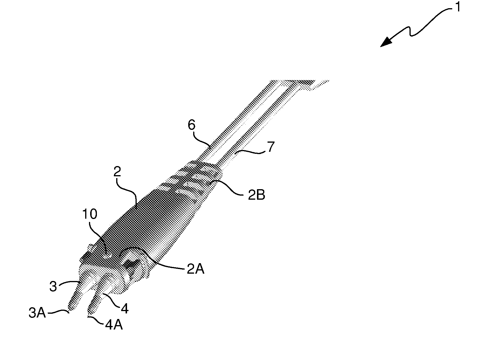
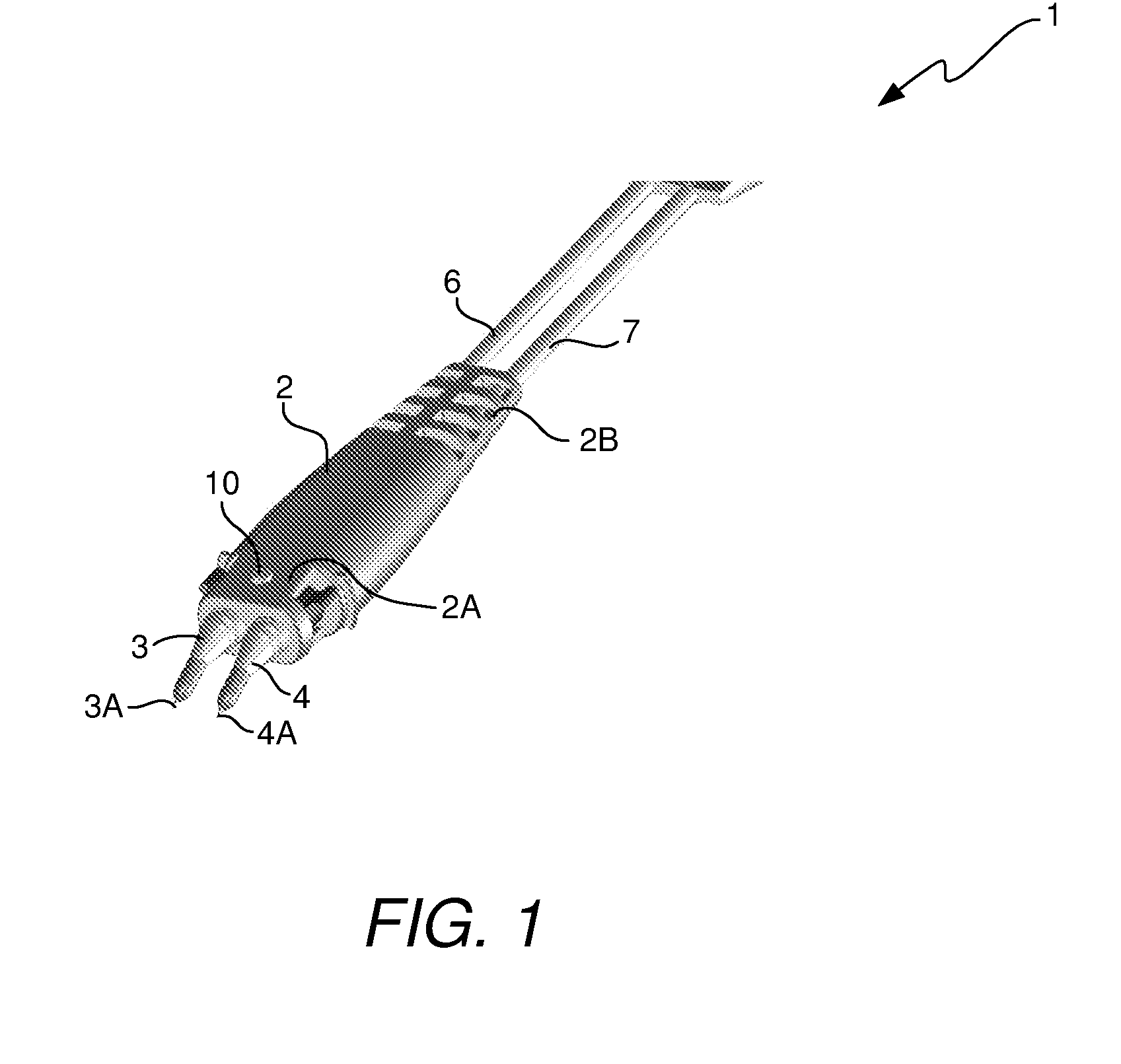
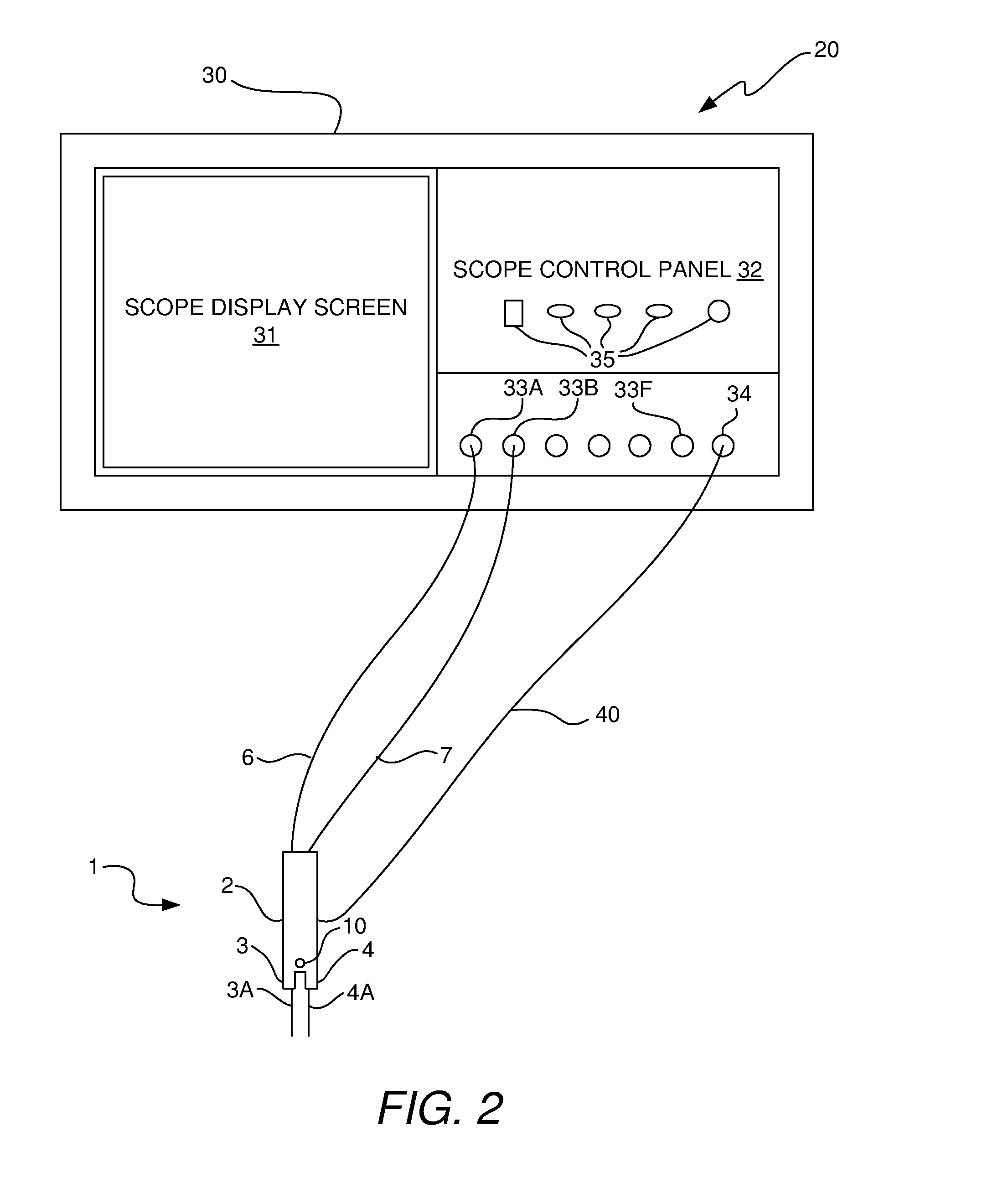
[0019]In accordance with the invention, a probe device is provided that has a light source thereon. In accordance with an embodiment, the light source operates as a visual indicator to provide a visual indication of whether a good connection exists between the tips of the probe device and the intended contact points on the DUT. In accordance with another embodiment, the light source operates as a source of illumination to illuminate the probe tips and the contact pads on the DUT as the user is attempting to place the probe tips in contact with the contact pads on the DUT. In accordance with another embodiment, the light source performs the dual functions of providing a visual indication of connection status and of illuminating the probe device tips and the intended contact points on the DUT.

[0020]A variety of probe device configurations are possible that will enable the goals of the invention to be achieved. A few examples of possible configurations will now be described with refere...


PUM


Abstract

A probe device is provided that has light source thereon that can be activated and deactivated. In accordance with an embodiment, the light source operates as a visual indicator to provide a visual indication of whether a good connection exists between the tips of the probe device and the intended contact points on the DUT. In accordance with another embodiment, the light source operates as a source of illumination to illuminate the probe tips and the contact pads on the DUT as the user is attempting to place the probe tips in contact with the contact pads on the DUT. In accordance with yet another embodiment, the light source performs the dual functions of providing a visual indication of connection status and of illuminating the probe device tips and the intended contact points on the DUT.

Description

TECHNICAL FIELD OF THE INVENTION[0001]The invention relates to electrical probe devices used to measure electrical signals on conductors of a device under test (DUT). More particularly, the invention relates to a probe device having a light source located thereon.BACKGROUND OF THE INVENTION[0002]A probe device is a device having two arms, sometimes referred to as “substrates” or “blades”, which are mechanically coupled to each other at distal ends of the arms, and having electrically conductive tips secured to the proximal ends of the arms. During testing of a DUT, the tips are placed in contact with respective conductors of the DUT for sensing electrical signals propagating though the conductors of the DUT. The probe device is typically adjustable to allow the probe tips to be moved closer to and farther away from each other such that a span width between the tips is adjustable to accommodate varying DUT physical layouts. The electrical signals sensed by the tips are passed from th...

Claims


Application Information

Patent Timeline
Patent Type & Authority Applications(United States)
IPC IPC(8): G01R1/067
CPCG01R1/06788
Inventor SWAIM, JASON A.CANNON, JAMES E.JOHNSON, KENNY
Owner AGILENT TECH INC
Why Eureka
Try Eureka