Method incorporating a tip into an endovascular device

a technology of endovascular devices and tips, which is applied in the direction of metal-working devices, catheters, tube connectors, etc., can solve the problem of more difficult to pass a guidewire therethrough

Active Publication Date: 2009-08-25
COOK MEDICAL TECH LLC
View PDF4 Cites 4 Cited by
  • Summary
  • Abstract
  • Description
  • Claims
  • Application Information

AI Technical Summary

Benefits of technology

[0005]A method of incorporating an endovascular device tip is disclosed. This method comprises incorporating a tip into an endovascular device comprising by providing a tubular end portion of an endovascular device comprising a distal end portion and at least one longitudinal bore extending therethrough. The distal end portion comprising at least one outlet opening and at least one longitudinal bore having an internal diameter. The method further includes creating a counterbore through the distal end of the tubular end portion, thereby increasing the internal diameter of at least one longitudinal bore, providing a tip having at least a first and second flange, and positioning the first flange within the counterbore and the second flange adjacent an outer surface of the tubular end portion, the tip having a first end and a second end.

Problems solved by technology

Therefore, it is desirable to develop a method of incorporating the tip of an endovascular device without changing the inner diameter of the tip, which would make it more difficult to pass a guidewire therethrough.

Method used


Image

  • Method incorporating a tip into an endovascular device
  • Method incorporating a tip into an endovascular device
  • Method incorporating a tip into an endovascular device

Examples


Embodiment Construction

[0025]An exemplary embodiment of the present invention may be described in use with any endovascular device, but for the purposes of this application, will be referred to as a catheter. To be clear, the tip assembly will be described in accordance with the following method, but other methods are contemplated by the invention.

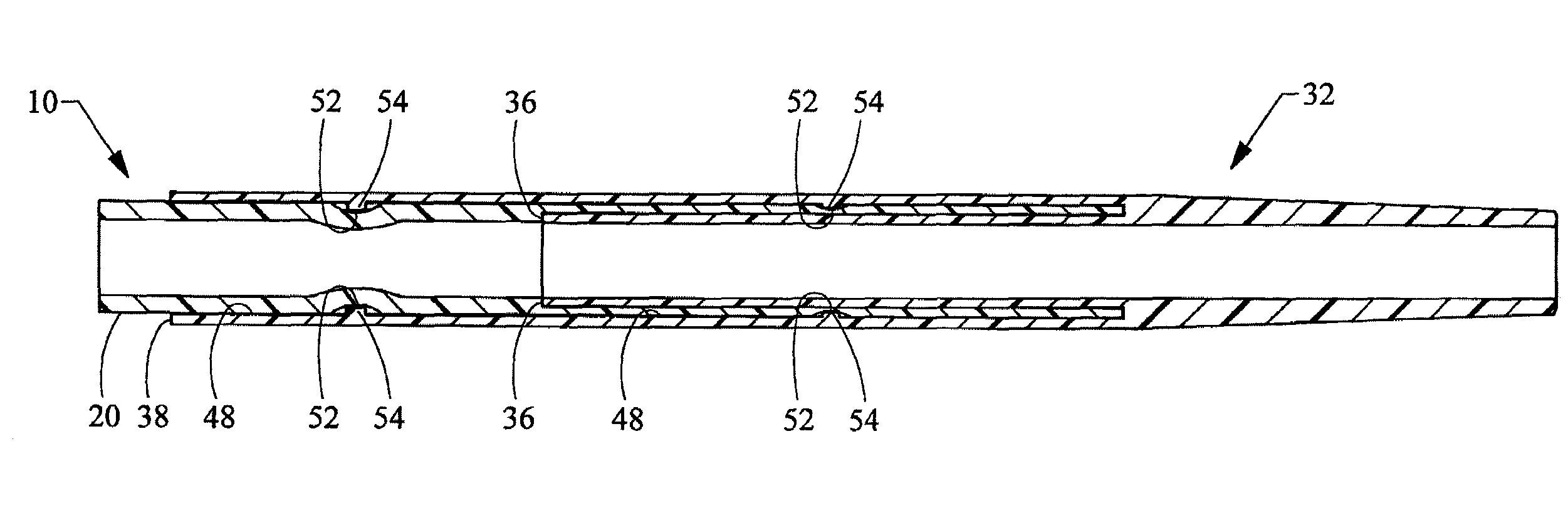
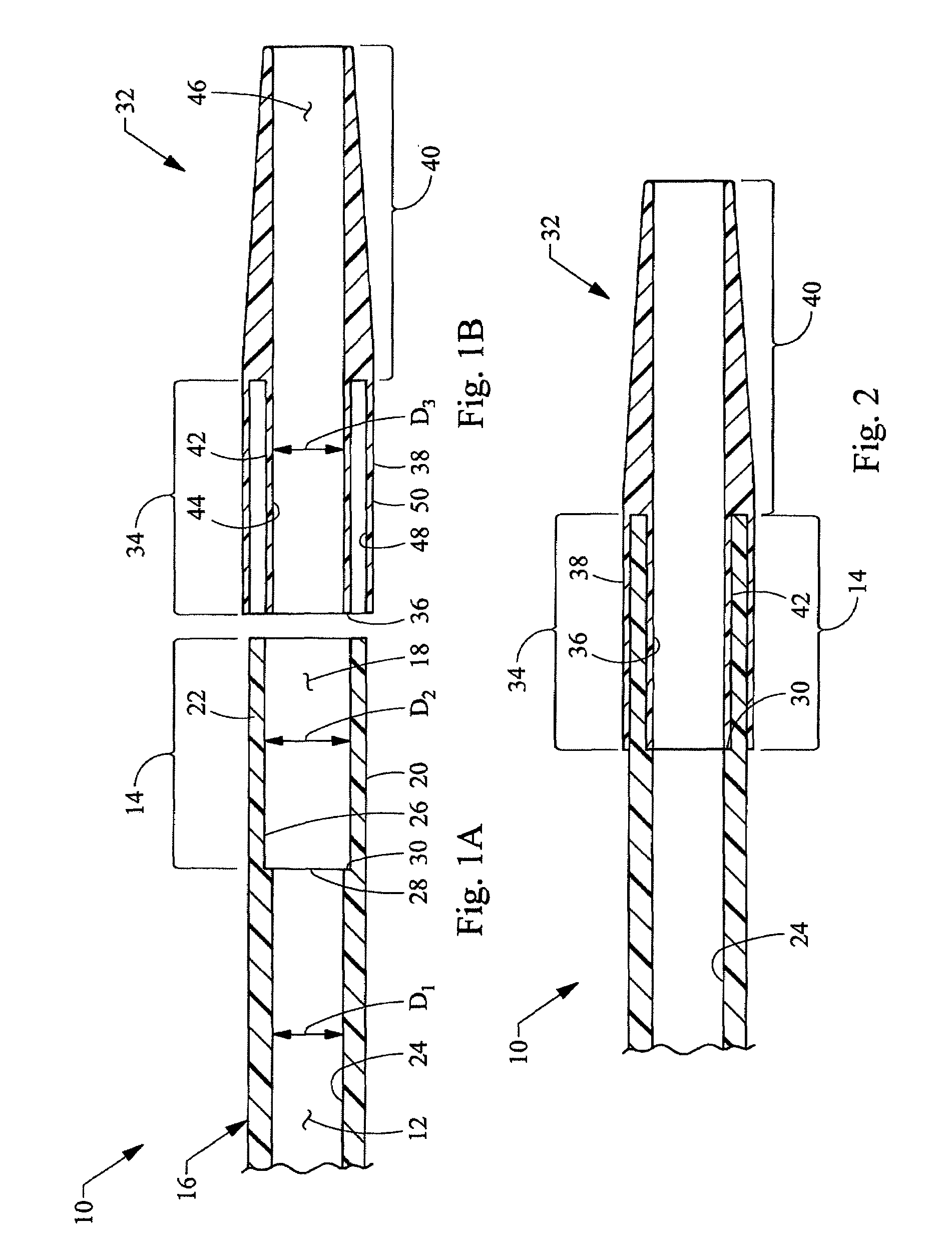
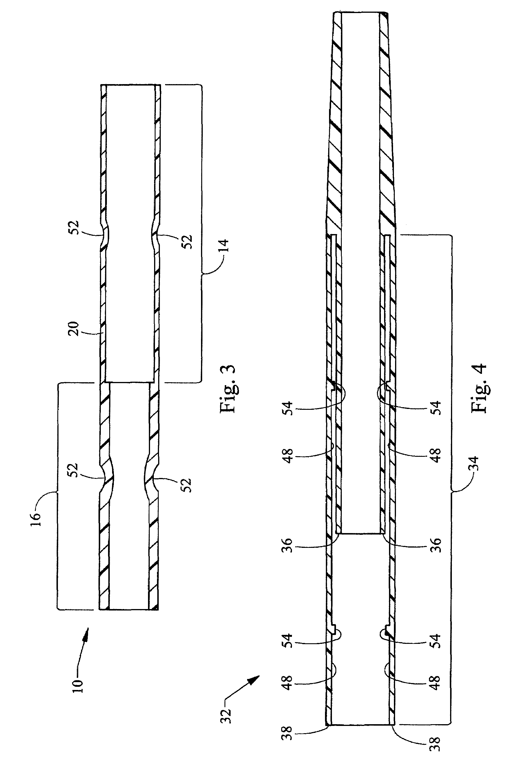
[0026]Referring now to FIGS. 1A and 1B, a method for incorporating a tip of an endovascular device into, for example a catheter, includes providing a tubular end portion 10 of any desired length having a primary bore 12 for directing fluids or mechanical devices, such as stents, to and from the body of the patient. The tubular end portion 10 may be integral with the catheter body of a single lumen catheter system, such as a balloon catheter. On catheter based systems that include multiple lumens, the distal end portion may be integral with the innermost lumen. Alternatively, the tubular end portion 10 may be glued or heat molded to the outermost catheter body. T...


PUM

PropertyMeasurementUnit
internal diameteraaaaaaaaaa

Abstract

An endovascular device tip assembly and method of making the same, incorporating a tip device with a first and second flange, usable with catheters and other suitable endovascular devices is provided. The tip assembly incorporates a tip device by providing a counterbore within a primary bore of a tubular end portion of an endovascular device. The tip device is fitted securely within the counterbore by placing the first flange within the counterbore and the second flange on the outside of the end portion.

Description

BACKGROUND[0001]The present application relates to an endovascular device tip assembly. Moreover, this application relates to the use of a low profile tip which is disposed at the end of a medical device, such as a catheter, by counterboring the distal end of a tubular device and placing the tip within.[0002]Endovascular devices have long been known which can be surgically inserted into a body lumen, such as an artery, to reinforce, support, repair, or otherwise enhance the performance of the lumen. For example, catheters generally include a hollow tubular portion, usually formed of resilient plastic, for insertion through the skin of a patient into a cavity, duct or vessel to permit injection or withdrawal of fluids, or to deliver medications to patients for therapeutic reasons.[0003]Typically, the distal tip of an endovascular device consists of a hollow metal or polymer cylinder which is tapered along the outer surface. The inside diameter of the tip is typically sized to allow t...

Claims


Application Information

Patent Timeline
Patent Type & Authority Patents(United States)
IPC IPC(8): A61M25/16B23P11/00
CPCA61M25/001A61M25/0069Y10T29/49936Y10T29/49995
Inventor MAGNUSON, MARK A.
Owner COOK MEDICAL TECH LLC
Why Eureka
Try Eureka