Antenna apparatus

a technology of antenna apparatus and antenna, which is applied in the direction of electrically short antennas, antennas, electrical apparatus, etc., can solve the problems of difficult to achieve a thinner antenna apparatus and the antenna apparatus b>100/b> becoming larger, and achieves a broader band of sending and receiving sensitivity, small and thin

Inactive Publication Date: 2009-08-20
MITSUMI ELECTRIC CO LTD
View PDF7 Cites 17 Cited by
  • Summary
  • Abstract
  • Description
  • Claims
  • Application Information

AI Technical Summary

Benefits of technology

[0013]It is, therefore, a main object of the present invention to provide an antenna apparatus which can be smaller and thinner, and also have a broader band of sending and receiving sensitivity.

Problems solved by technology

Therefore, it is difficult to achieve a thinner antenna apparatus, at least by shortening the distance between the dipole antenna DA and the parasitic device E, and there is a problem that the antenna apparatus 100 becomes larger for a purpose such as setting indoors.

Method used


Image

  • Antenna apparatus
  • Antenna apparatus
  • Antenna apparatus

Examples


Embodiment Construction

[0031]The best mode for carrying out the antenna apparatus according to the present invention will be explained in detail with reference to the drawings. However, the scope of the invention is not limited by the illustrated examples.

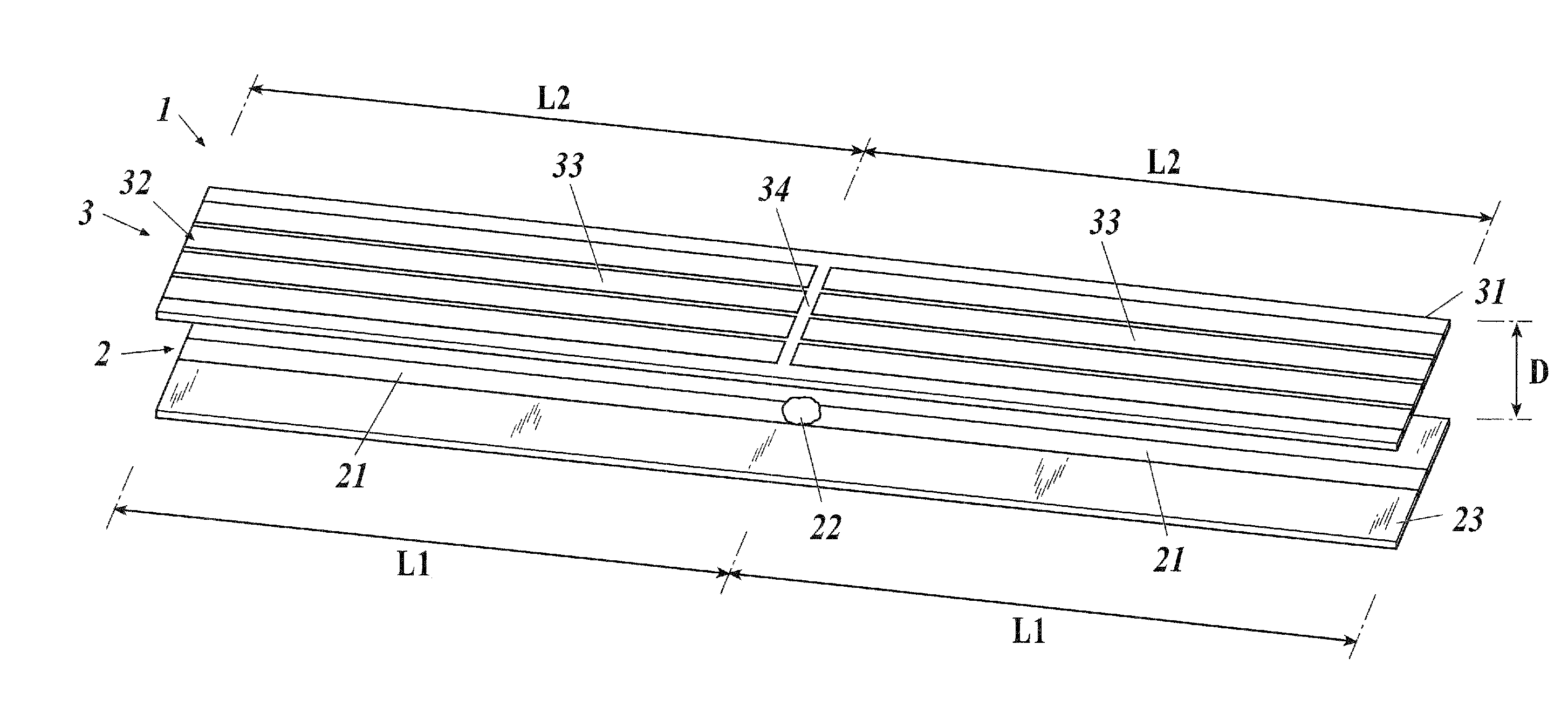
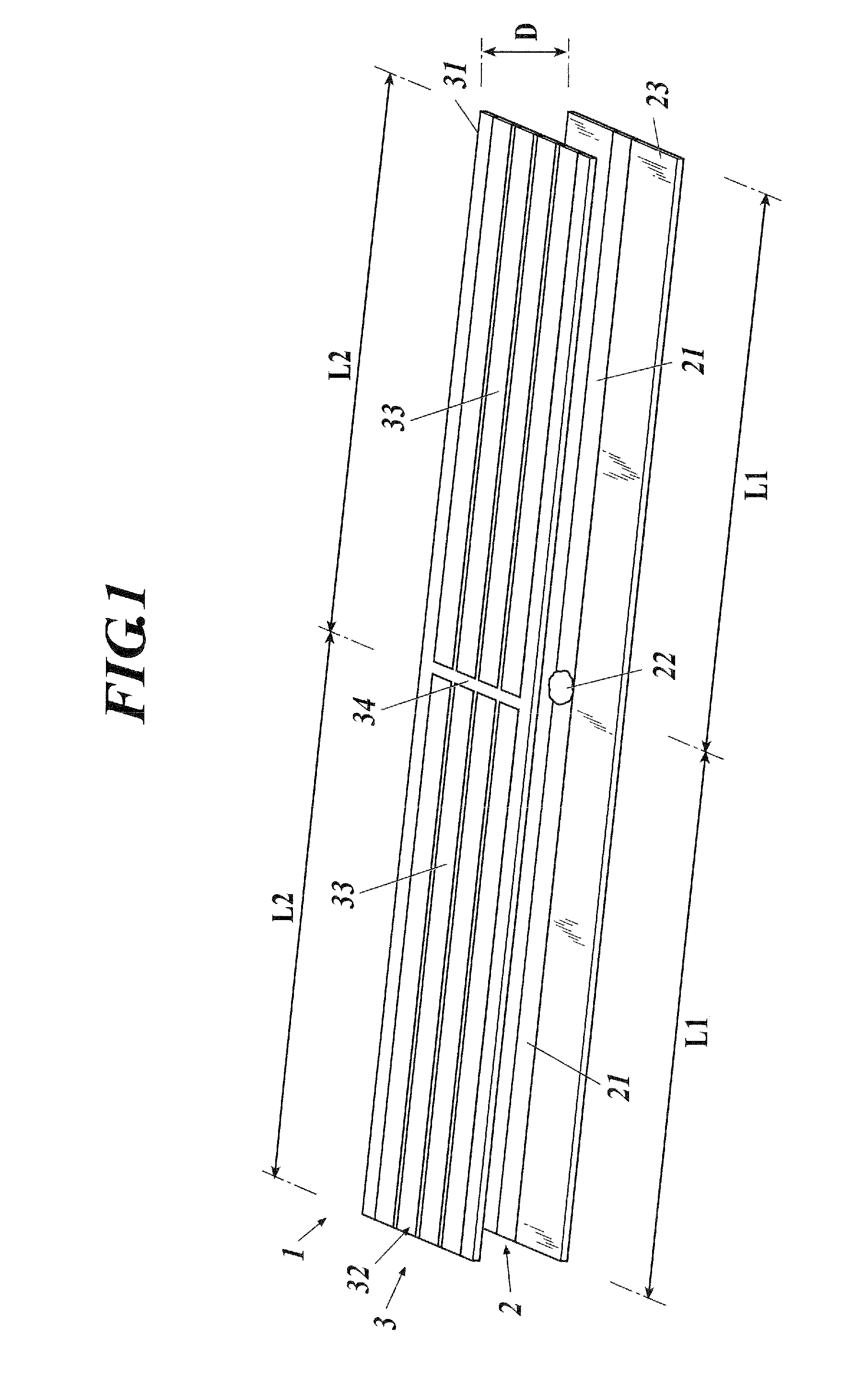
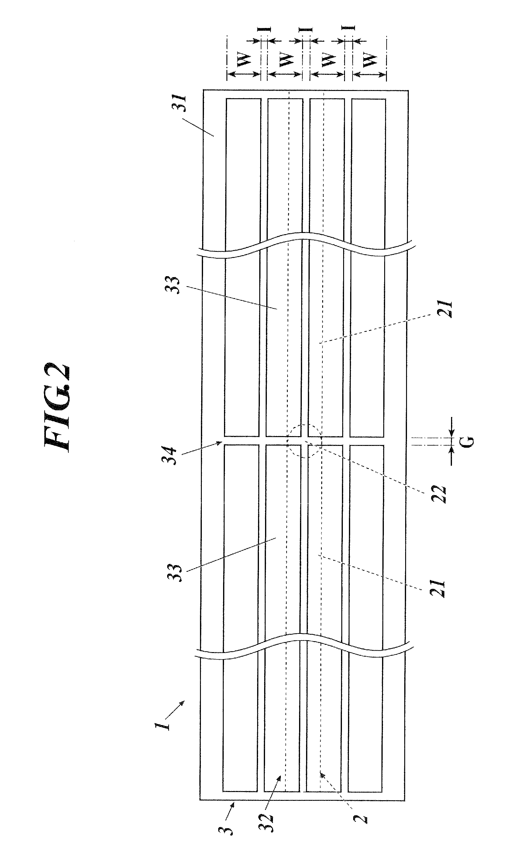
[0032]As shown in FIG. 1, the antenna apparatus 1 of the present invention includes an antenna device 2 and a parasitic device 3. In the embodiment below, an example where the antenna device 2 is composed of a dipole antenna is explained.

[0033]The antenna device 2 includes a pair of antenna elements 21 and 21 placed symmetrically on a straight line and includes a feeding point 22 at a portion connecting the pair of antenna elements 21 and 21, in other words, at a center portion in an extending direction of the pair of antenna elements 21 and 21. Length L1 of each of the antenna elements 21 is set for example, in a length of a quarter wavelength of a wavelength corresponding to a predetermined frequency within a UHF band (470 to 770 MHz) of terrestrial di...


PUM


Abstract

An antenna apparatus, including: an antenna device including a feeding point and a pair of antenna elements placed symmetrically with respect to the feeding point; and a parasitic device placed parallel to each of the antenna elements of the antenna device and including one or a plurality of elements placed at a position separated from each of the antenna elements, wherein the element of the parasitic device includes a gap at a center of the element in an extending direction and includes a pair of sub-elements structured symmetrically with respect to the gap as a boundary.

Description

BACKGROUND OF THE INVENTION[0001]1. Field of the Invention[0002]The present invention relates to an antenna apparatus, and in particular, an antenna apparatus including a dipole antenna and a parasitic device.[0003]2. Description of Related Art[0004]A Yagi-Uda Antenna is known as an antenna apparatus for sending and receiving television broadcasting, etc. Typically, the Yagi-Uda Antenna is configured by combining a dipole antenna which is a fed radiator, and a parasitic director and reflector provided parallel to the dipole antenna. As shown in FIG. 10, an antenna apparatus 100 combining only a dipole antenna DA and parasitic device E is also broadly called a Yagi-Uda Antenna.[0005]As for the antenna apparatus 100 shown in FIG. 10, in order to reduce a size for a purpose such as for setting indoors, an object of consideration is use of the parasitic device E as a director where a distance d between the dipole antenna DA and the parasitic device E requires only a quarter wavelength.[...

Claims


Application Information

Patent Timeline
Patent Type & Authority Applications(United States)
IPC IPC(8): H01Q19/13
CPCH01Q1/24H01Q19/30H01Q9/285H01Q1/38
Inventor SATO, SHONAKANO, HISAMATSU
Owner MITSUMI ELECTRIC CO LTD
Why Eureka
Try Eureka