Mounting component for optical fiber, optical module, and optical module manufacturing method

a technology of mounting components and optical fibers, applied in the direction of optics, instruments, optical light guides, etc., can solve the problems of device absorption effects and higher fabrication cost of active alignment processes, and achieve the effect of higher precision

Active Publication Date: 2017-04-13
CITIZEN WATCH CO LTD
View PDF7 Cites 6 Cited by
  • Summary
  • Abstract
  • Description
  • Claims
  • Application Information

AI Technical Summary

Benefits of technology

[0029]The above mounting component for an optical fiber allows a laser device and an optical fiber to be aligned with higher precision while providing protection for the laser device mounted on a substrate. Further, the above optical module can be made smaller and thinner and can be fabricated at a lower cost than could be achieved without the configuration of the present invention.

Problems solved by technology

Generally, the active alignment process can achieve highly precise alignment compared with the passive alignment process, but the fabrication cost of the active alignment process is higher because the alignment process takes time.
In particular, in the case of a laser device that emits light at a relatively short wavelength, such as blue, the device must be hermetically sealed in order to also prevent accumulation of impurities on the light emitting part, because such a laser device is susceptible to absorption effects by light energy.

Method used


Image

  • Mounting component for optical fiber, optical module, and optical module manufacturing method
  • Mounting component for optical fiber, optical module, and optical module manufacturing method
  • Mounting component for optical fiber, optical module, and optical module manufacturing method

Examples


Embodiment Construction

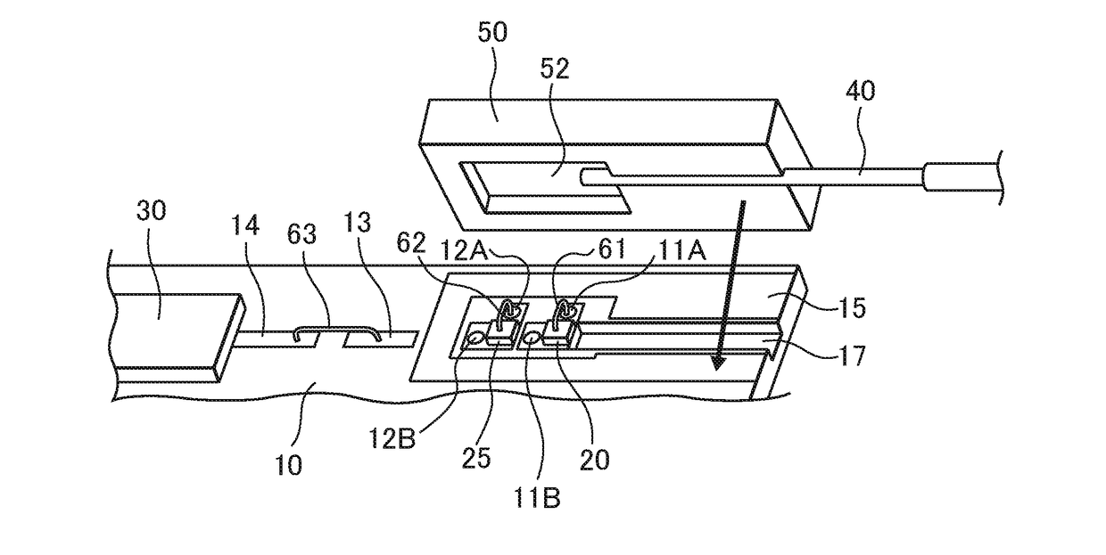
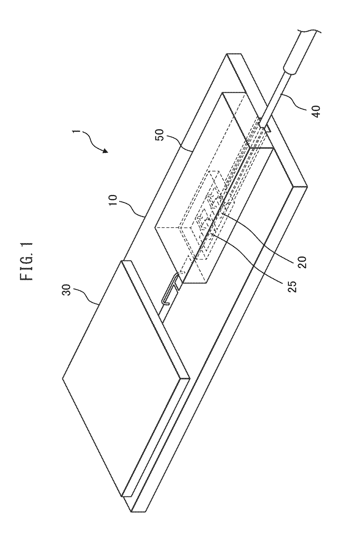
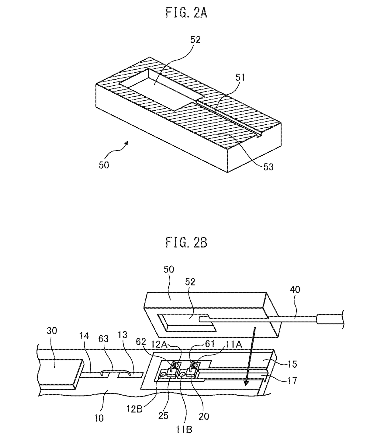
[0087]Hereinafter, with reference to the accompanying drawings, a mounting component for optical fiber, optical module, and fabrication method will be explained in detail. However, it should be noted that the present invention is not limited to the drawings or the embodiments described below.

[0088]This mounting component functions not only as a fiber submount substrate (hereinafter referred to simply as a “sub-substrate”) formed, for example, from silicon but also as a protective component (cover) for a laser device mounted on a mounting substrate. Silicon is transmissive to near-infrared radiation; therefore, when the mounting component is mounted with its bonding surface in contact with the mounting substrate so as to cover the laser device, the position of the laser device can be observed using an infrared camera. Accordingly, the laser device and the optical fiber can be centered and aligned with respect to each other while monitoring a near-infrared transmission image through t...


PUM


Abstract

Provided is a mounting component for an optical fiber that allows a laser device and an optical fiber to be aligned with higher precision while providing protection for the laser device mounted on a substrate. The a mounting component is a component formed from silicon for optically coupling a laser device to an optical fiber by being bonded to a mounting substrate on which the laser device is mounted, and includes a groove portion for fixedly holding the optical fiber so that a core of the optical fiber is positioned at a predetermined depth with respect to a bonding surface to be bonded to the mounting substrate, and a recessed portion, formed continuous with the groove portion, for accommodating the laser device, wherein a thickness of the mounting component, measured in a direction perpendicular to the bonding surface, is chosen so that a position of the laser device can be detected using an infrared transmission image when the laser device is accommodated in the recessed portion by placing the bonding surface in contact with the mounting substrate.

Description

TECHNICAL FIELD[0001]The present invention relates to a mounting component for an optical fiber, an optical module, and a fabrication method for the same.BACKGROUND ART[0002]In an optical module in which light from a laser device is directly introduced (i.e., optically coupled) into an optical fiber, the laser device and the optical fiber must be centered and aligned with respect to each other in order to increase optical coupling efficiency. This alignment process can be accomplished in two ways: passive alignment in which the relative position between the laser device and the optical fiber is adjusted by reference to a preset alignment mark, and active alignment in which the laser device is caused to emit light and the relative position is adjusted while monitoring the light output coupled into the optical fiber. Generally, the active alignment process can achieve highly precise alignment compared with the passive alignment process, but the fabrication cost of the active alignment...

Claims


Application Information

Patent Timeline
Patent Type & Authority Applications(United States)
IPC IPC(8): G02B6/42
CPCG02B6/4221G02B6/4243G02B6/4239G02B6/4251G02B6/4232G02B6/4242G02B6/4224G02B6/4238
Inventor YODA, KAORUIDE, MASAFUMI
Owner CITIZEN WATCH CO LTD
Why Eureka
Try Eureka