Slide connector

a technology of sliding connectors and connectors, which is applied in the direction of coupling contact members, coupling device connections, travelling carriers, etc., can solve the problems of short circuit at the contact portion, reducing the thickness of the connector, and hammering the miniaturization of the wearable device, so as to reduce the burden on the wearer's body and small and thin wearable devices

Active Publication Date: 2018-06-21
JAPAN AVIATION ELECTRONICS IND LTD
View PDF3 Cites 5 Cited by
  • Summary
  • Abstract
  • Description
  • Claims
  • Application Information

AI Technical Summary

Benefits of technology

[0010]The present invention has been made in order to solve the conventional drawbacks described above and is aimed at providing a slide connector that enables a small and thin wearable device to be achieved, reduces a burden on a wearer's body in a connecting process and prevents water from entering.
[0017]wherein, when the module-side connector portion is overlapped on the garment-side connector portion and slid along the fitting plane from a first position to a second position, each of the contact portions of the second contacts comes into contact with a corresponding one of the contact surfaces of the first contacts to establish electrical connection, the portion to be locked comes into contact with the locking surface of the locking portion whereby the module-side connector portion is fitted with the garment-side connector portion, and the waterproof member is elastically compressed to thereby prevent water from entering portions at which the contact surfaces of the first contacts and the contact portions of the second contacts are in contact with each other.

Problems solved by technology

In the snap button connector of JP 2015-135723 A, however, since the entire male snap button 2 and the entire female snap button 4 each function as a single electrode, connections of a plurality of wires would require attachment of as many snap button connectors as the number of the wires to a garment, which hampers miniaturization of a wearable device.
Aside from that, while the connector needs to be thin because it electrically connects the first cloth 1 to the second cloth 3, the snap button connector of JP 2015-135723 A has the configuration in which the convex portion 5 of the male snap button 2 is fitted in the concave portion 6 of the female snap button 4 in the direction orthogonal to a surface of the garment, and this is disadvantageous from the standpoint of reducing the connector in thickness.
Accordingly, there is a problem in that, even if the connector is only slightly exposed to water in a living environment, an attached water drop easily causes a short-circuit at the contact portion.

Method used


Image

  • Slide connector
  • Slide connector
  • Slide connector

Examples


embodiment 1

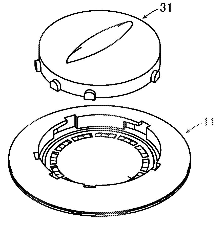
[0063]FIG. 1 shows the structure of a slide connector according to Embodiment 1. The slide connector includes a garment-side connector portion 11 to be attached to a garment and a module-side connector portion 31 to be fitted with the garment-side connector portion 11.

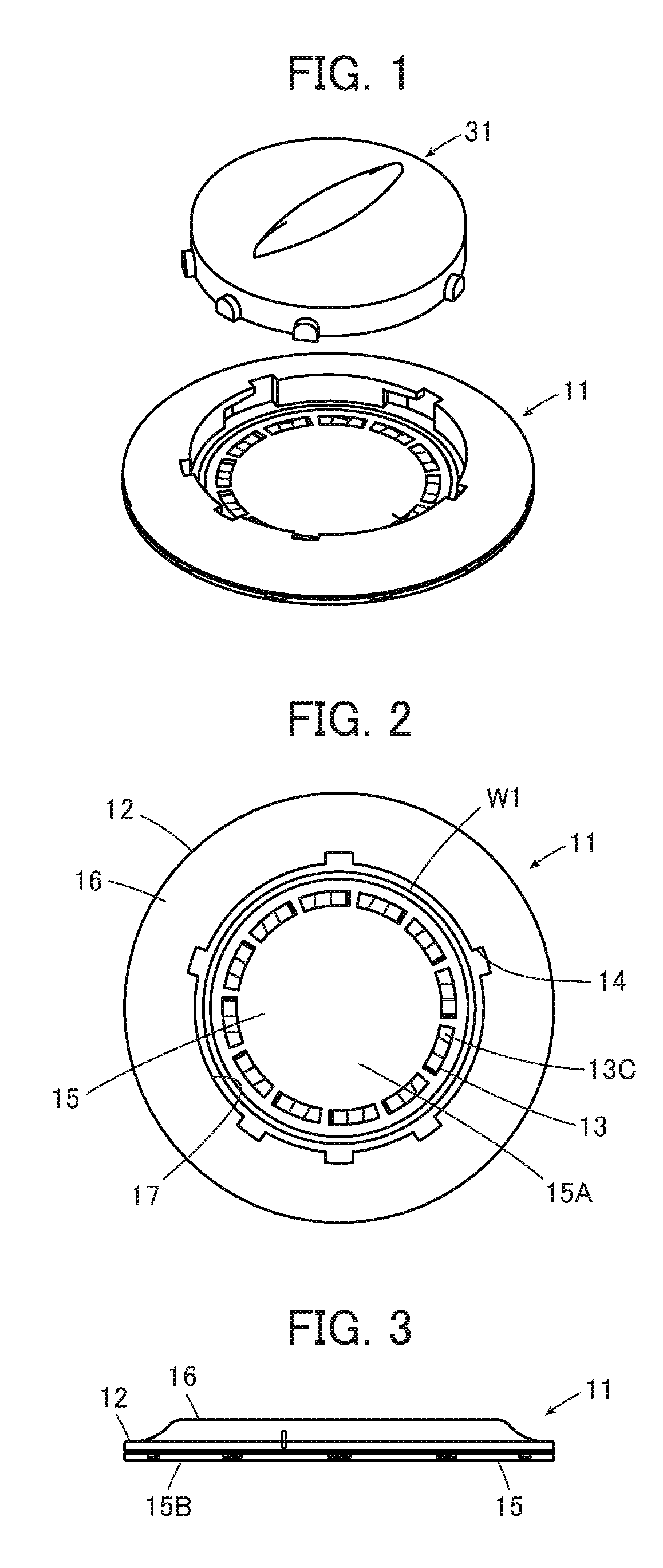
[0064]As shown in FIGS. 2 and 3, the garment-side connector portion 11 includes a garment-side connector body 12 of disk shape, a plurality of first contacts 13 arranged in the garment-side connector body 12, a plurality of locking portions 14 formed in the garment-side connector body 12, and a first waterproof member W1 of annular shape disposed in the garment-side connector body 12.

[0065]The garment-side connector body 12 is composed of a base member 15 of disk shape and a frame member 16. A surface of the base member 15 forms a garment-side reference surface 15A, and the frame member 16 is attached to the outer edge of the garment-side reference surface 15A. The frame member 16 has a circular frame shape with an ope...

embodiment 2

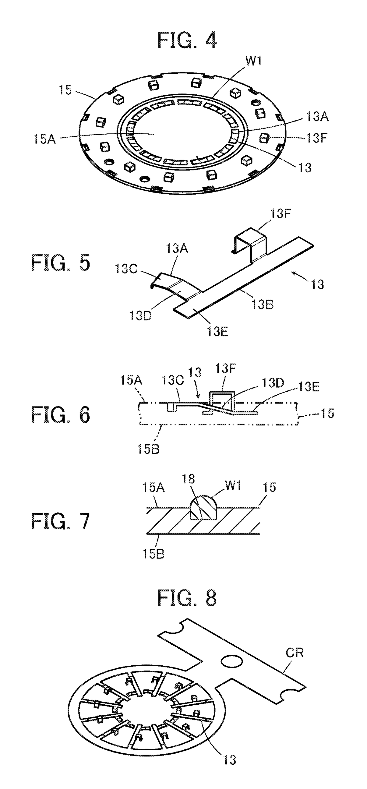
[0121]In Embodiment 1 above, the contact portions 33A of the spring-like second contacts 33 of the module-side connector portion 31 project from the module-side reference surface 35A, and correspondingly, the contact surfaces 13C of the first contacts 13 of the garment-side connector portion 11 have a substantially same height as the garment-side reference surface 15A of the base member 15 while the flat surfaces 13E are located lower than the garment-side reference surface 15A of the base member 15 to be closer to the bottom surface 15B; however, the invention is not limited thereto.

[0122]FIG. 25 shows a garment-side connector portion 41 and a module-side connector portion 51 that constitute a slide connector according to Embodiment 2. The garment-side connector portion 41 is the same as the garment-side connector portion 11 used in Embodiment 1 except that a base member 45 is used instead of the base member 15 and first contacts 43 are used instead of the first contacts 13. The fi...

embodiment 3

[0136]While in Embodiment 1, the first waterproof member W1 surrounding the contact surfaces 13C of the first contacts 13 is disposed on the garment-side reference surface 15A of the garment-side connector portion 11, the invention is not limited thereto.

[0137]In Embodiment 3, the first waterproof member W1 is not provided on a garment-side reference surface 61A of a garment-side connector portion 61 as shown in FIG. 35, and as shown in FIG. 36, a second waterproof member W2 having a closed shape surrounding the contact portions 33A of the spring-like second contacts 33 is disposed on a module-side reference surface 62A of a module-side connector portion 62. As shown in FIG. 37, the second waterproof member W2 projects from the module-side reference surface 62A.

[0138]Except for not having the first waterproof member W1 on the garment-side reference surface 61A, the garment-side connector portion 61 has the same configuration as the garment-side connector portion 11 in Embodiment 1, ...


PUM


Abstract

A slide connector includes a garment-side connector portion and a module-side connector portion,the garment-side connector portion includes a garment-side connector body, first contacts having contact surfaces parallel to a fitting plane, and a locking portion having a locking surface,the module-side connector portion includes a module-side connector body, spring type second contacts having contact portions displaceable in a direction orthogonal to the fitting plane, and a portion to be locked,one of the garment-side connector portion and the module-side connector portion having an elastically deformable waterproof member that is located in the fitting plane and has a closed shape surrounding the contact surfaces of the first contacts or the second contacts.

Description

BACKGROUND OF THE INVENTION[0001]The present invention relates to a slide connector, particularly to a slide connector that is connected to a wearable device.[0002]In recent years, so-called wearable devices in which terminal devices such as various sensors and communication devices operate as being worn by a user have attracted attention. Such a wearable device is electrically connected to a device like a measuring device or a power source to transmit detected information or receive power supply. While electrical connection can be established via a connector attached to a garment, the connection via the connector has to be disconnected when the wearable device is detached, when the garment is washed, and on other occasions.[0003]To cope with it, for instance, a snap button connector has been used to establish connection between devices as disclosed in JP 2015-135723 A.[0004]As shown in FIG. 44, the snap button connector disclosed in JP 2015-135723 A includes a male snap button 2 at...

Claims


Application Information

Patent Timeline
Patent Type & Authority Applications(United States)
IPC IPC(8): H01R24/00H01R13/24H01R13/52
CPCH01R24/005H01R13/245H01R13/5219H01R2107/00H01R2201/20H01R13/52H01R13/629H01R13/639H01R13/665H01R13/73A41D1/002H01R13/24H01R13/2442H01R13/625A45F5/02A45F2200/055
Inventor KOMOTO, TETSUYAMATSUNAGA, AKIHIRO
Owner JAPAN AVIATION ELECTRONICS IND LTD
Why Eureka
Try Eureka