Transmission line and electronic device

a transmission line and electronic device technology, applied in the direction of waveguides, waveguides, electrical apparatus casings/cabinets/drawers, etc., can solve the problems of difficult high-frequency signals transmitted through the respective individual transmission portions, and achieve high isolation and reduce transmission losses.

Active Publication Date: 2015-11-05
MURATA MFG CO LTD
View PDF2 Cites 4 Cited by
  • Summary
  • Abstract
  • Description
  • Claims
  • Application Information

AI Technical Summary

Benefits of technology

[0043]In this configuration, the electronic device that utilizes one of the above-mentioned transmission lines is illustrated. Using one of the above-mentioned transmission lines, it is possible to secure high isolation between a plurality of transmission lines (individual transmission portions) that perform transmission. Therefore, it is possible to reduce transmission losses in a case where various kinds of high-frequency signals are transmitted between the circuit elements.
[0044]According to various preferred embodiments of the present invention, it is possible to provide a small and thin transmission line capable of transmitting a plurality of high-frequency signals in a state in which high isolation between the high-frequency signals is secured.

Problems solved by technology

Therefore, it is difficult for high-frequency signals transmitted through the respective individual transmission portions to be electromagnetic-field-coupled to each other.

Method used


Image

  • Transmission line and electronic device
  • Transmission line and electronic device
  • Transmission line and electronic device

Examples


Embodiment Construction

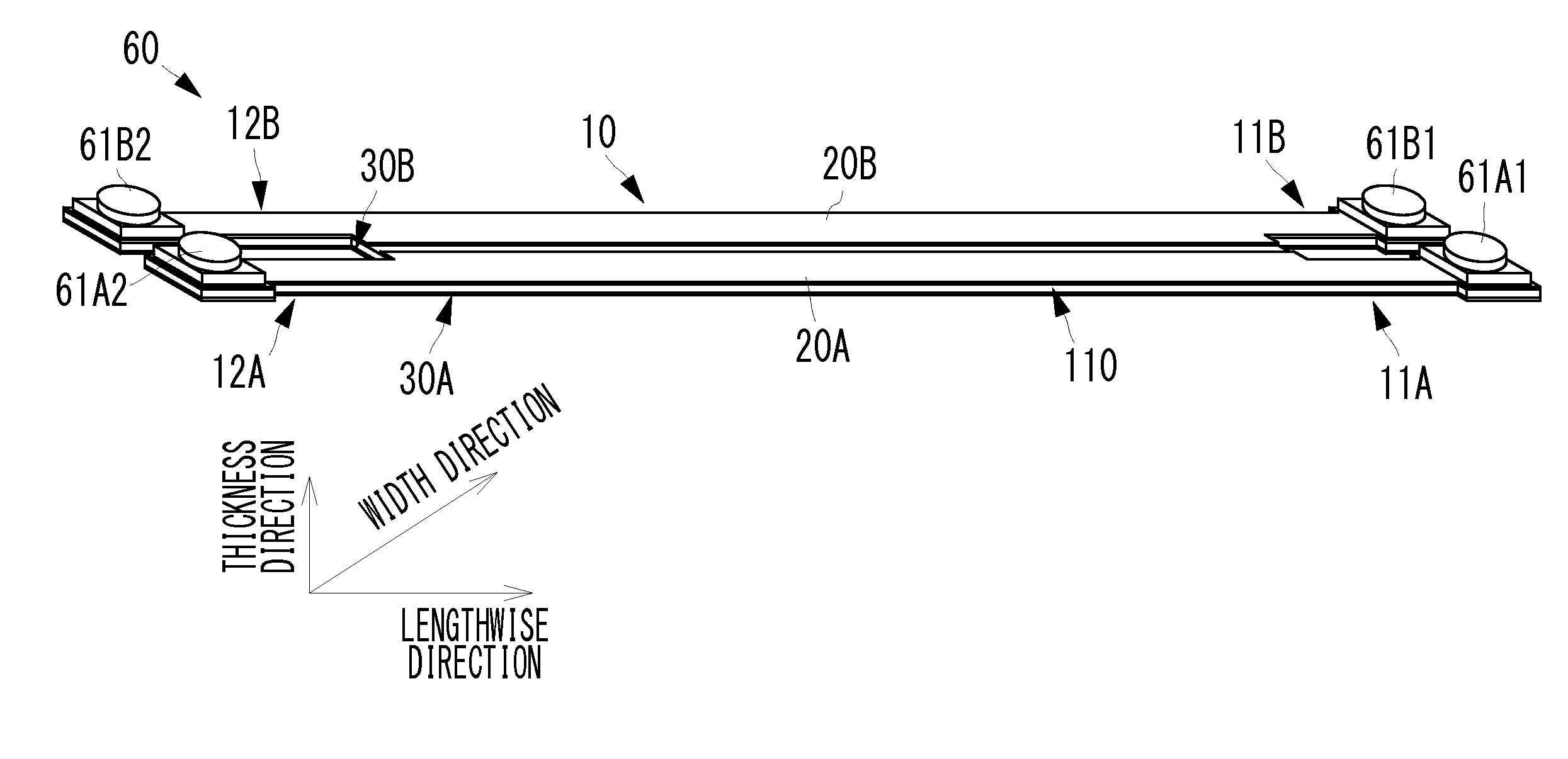
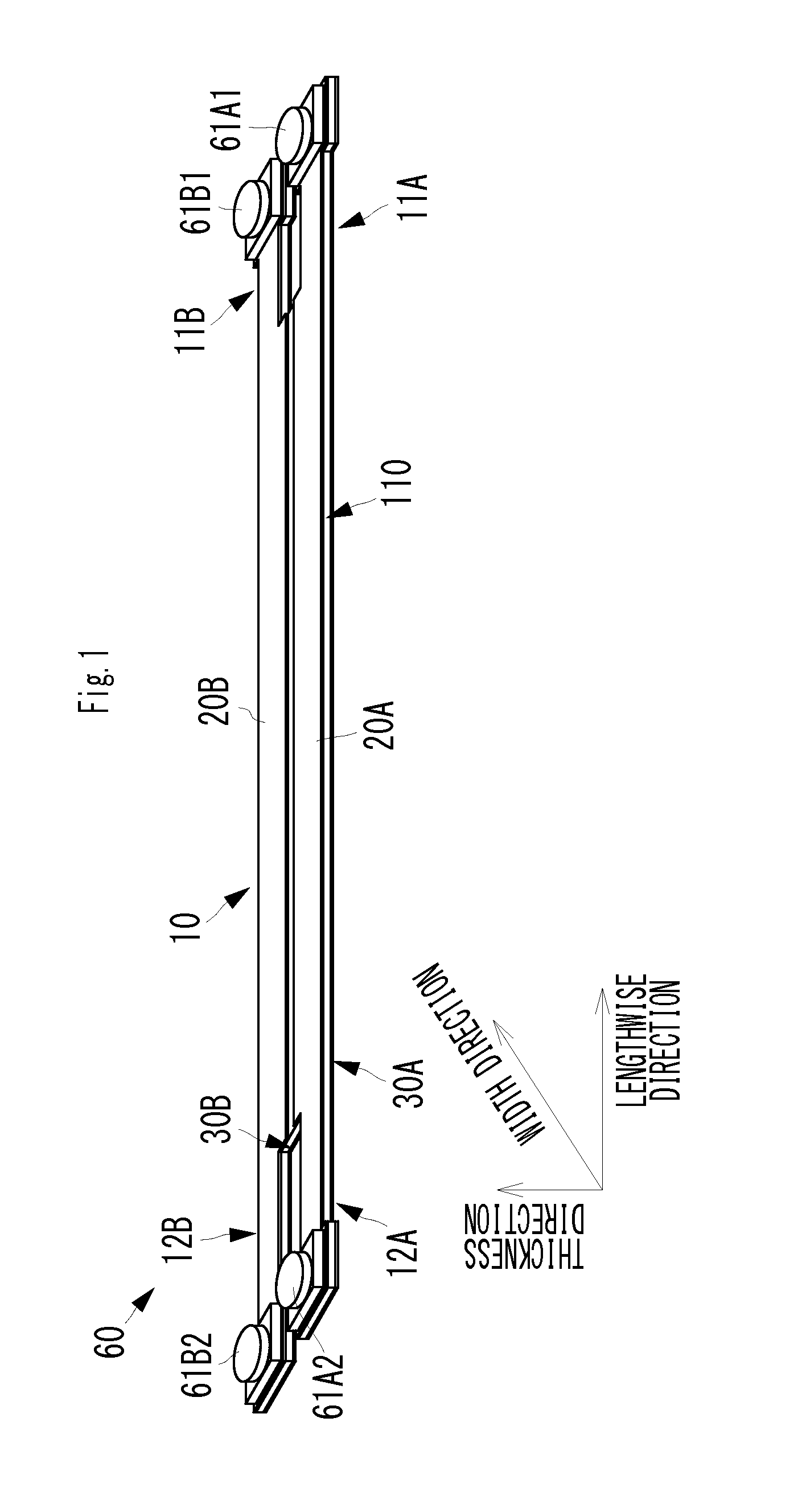
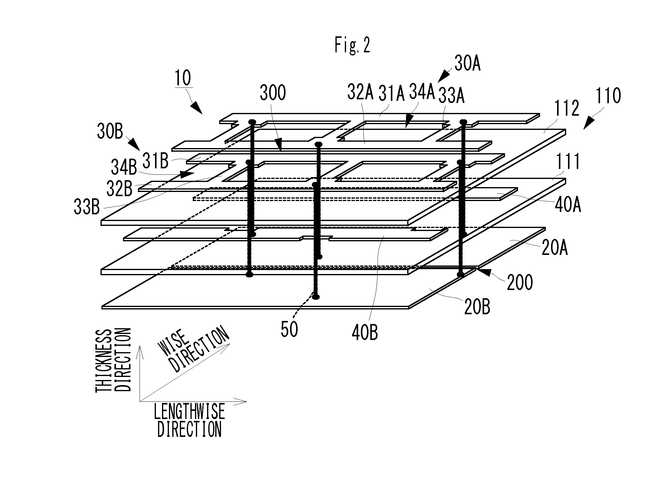
[0057]A transmission line according to a first preferred embodiment of the present invention will be described with reference to drawings. FIG. 1 is the external perspective view of a flat cable including the transmission line according to the first preferred embodiment of the present invention. FIG. 2 is an exploded perspective view illustrating the structure of a main transmission line portion according to the first preferred embodiment of the present invention. FIGS. 3A to 3C are exploded plan views illustrating the structure of the main transmission line portion according to the first preferred embodiment of the present invention. FIGS. 4A and 4B are cross-sectional views illustrating the structure of the main transmission line portion according to the first preferred embodiment of the present invention. FIG. 4A is a IVA-IVA cross-sectional view illustrated in FIGS. 3A to 3C, and FIG. 4B is a IVB-IVB cross-sectional view illustrated in FIGS. 3A to 3C.

[0058]In addition, in FIG. 1...


PUM


Abstract

A main transmission line includes a substantially elongated dielectric body in which first and second substantially elongated signal conductors are disposed with a distance therebetween in a width direction. A first reference ground conductor and a first auxiliary ground conductor sandwich therebetween the first signal conductor in a thickness direction. A second reference ground conductor and a second auxiliary ground conductor sandwich therebetween the second signal conductor in the thickness direction. The second auxiliary ground conductor includes two substantially elongated conductors and a first bridge conductor, and the second auxiliary ground conductor includes two substantially elongated conductors and a second bridge conductor. The positions of the first and second bridge conductors in a lengthwise direction are different.

Description

BACKGROUND OF THE INVENTION[0001]1. Field of the Invention[0002]The present invention relates to a thin transmission line configured to transmit a high-frequency signal and an electronic device including the transmission line.[0003]2. Description of the Related Art[0004]At present it attracts attention to use such a flat cable as illustrated in Japanese Patent No. 4962660 as a high-frequency transmission line for transmitting a high-frequency signal. While the flat cable is larger in width than a coaxial cable, it is possible to make the flat cable thin. Therefore, in particular the flat cable is useful in a case where there is only a thin clearance gap within a terminal housing. In addition, since a dielectric body having flexibility is used as a base material, the flat cable has flexibility and can easily adopt curved or flexed routing.[0005]The flat cable described in Japanese Patent No. 4962660 has a triplate-type strip line structure, as a basic structure.[0006]Such a flat cabl...

Claims


Application Information

Patent Timeline
Patent Type & Authority Applications(United States)
IPC IPC(8): H01P3/02H05K1/02H05K1/18
CPCH01P3/026H05K1/0242H05K1/18H01P3/085H05K1/0225H05K1/0227H05K1/025H05K1/028H05K1/147H05K2201/09618H05K2201/09727
Inventor YOSUI, KUNIAKIIKEMOTO, NOBUOTAGO, SHIGERUYANG, ZHUJUNSASAKI, JUNMATSUDA, FUMIETAMURA, WATARU
Owner MURATA MFG CO LTD
Why Eureka
Try Eureka