Physical Quantity Sensor and Lead Frame Used for Same

Inactive Publication Date: 2007-09-27
YAMAHA CORP
View PDF13 Cites 5 Cited by
  • Summary
  • Abstract
  • Description
  • Claims
  • Application Information

AI Technical Summary

Benefits of technology

[0028] When the stage portion, the physical quantity sensor chip, and the leads are integrally molded by a resin using a lead frame of this configuration, the resin formation space is filled with resin by sandwiching the frame portion with a metallic mold as well as disposing the stage portion, the physical quantity sensor chip, and the leads in the resin formation space within the metallic mold. At this time, the melted resin is flowed to the aforementioned resin formation space from, amongst the rectangular inner areas, one corner located on a diagonal line which intersects another diagonal line which becomes the array direction of the two stage portions, towards the other corner side. Since the stage portion and the physical quantity sensor chip are not located on the flow path of this resin, obstruction of the flow of the melted resin due to the stage portion, the physical quantity sensor chip, or the like, can be prevented.
[0029] Furthermore, a physical quantity sensor according to the present invention comprises: a stage portion mounting a physical quantit

Problems solved by technology

However, since the second magnetic sensor chip is mounted in a state where it is vertically standing with respect to the surface of the substrate, this magnetic sensor has an inconvenience in th

Method used


Image

  • Physical Quantity Sensor and Lead Frame Used for Same
  • Physical Quantity Sensor and Lead Frame Used for Same
  • Physical Quantity Sensor and Lead Frame Used for Same

Examples


Example

First Example

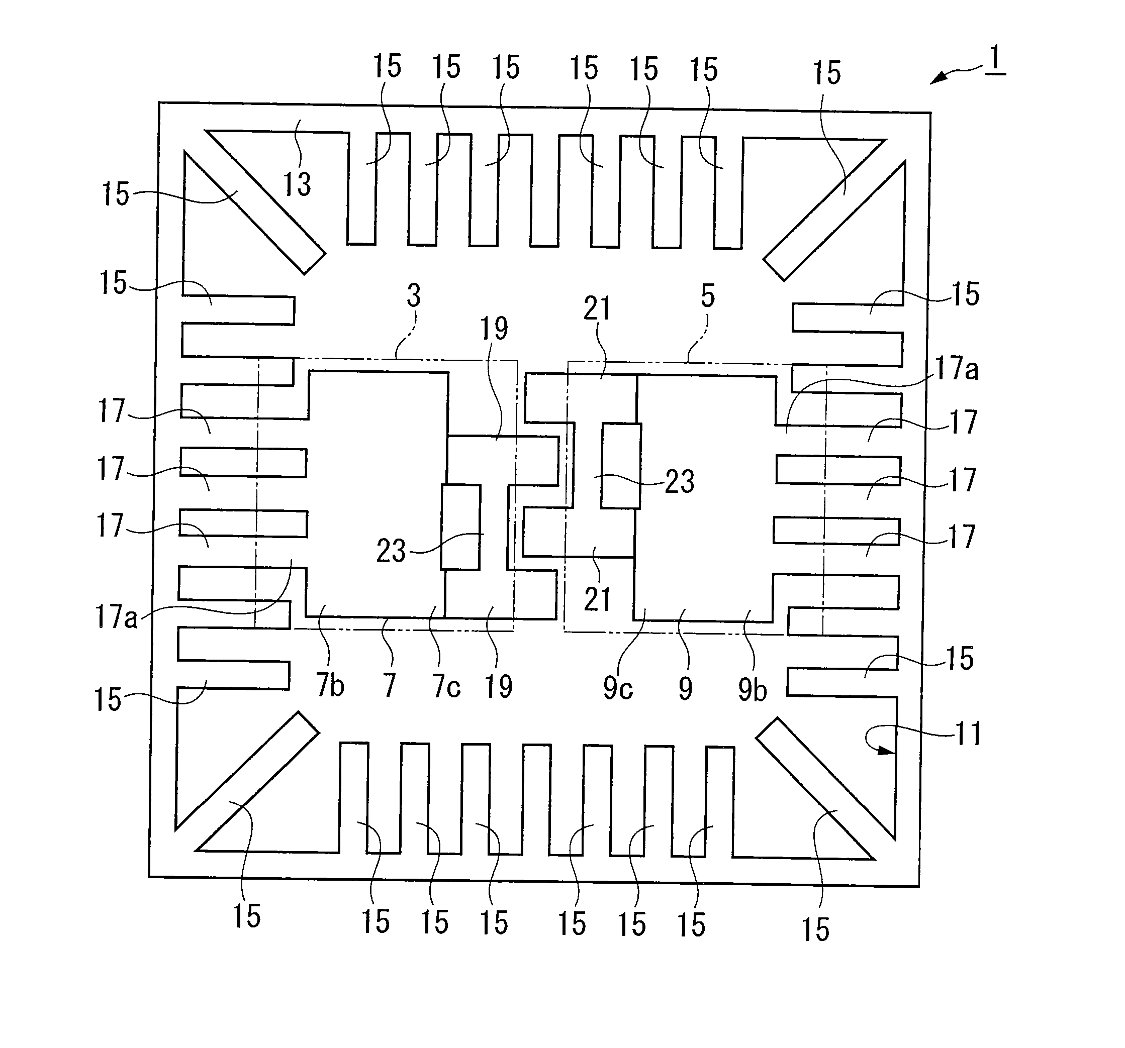
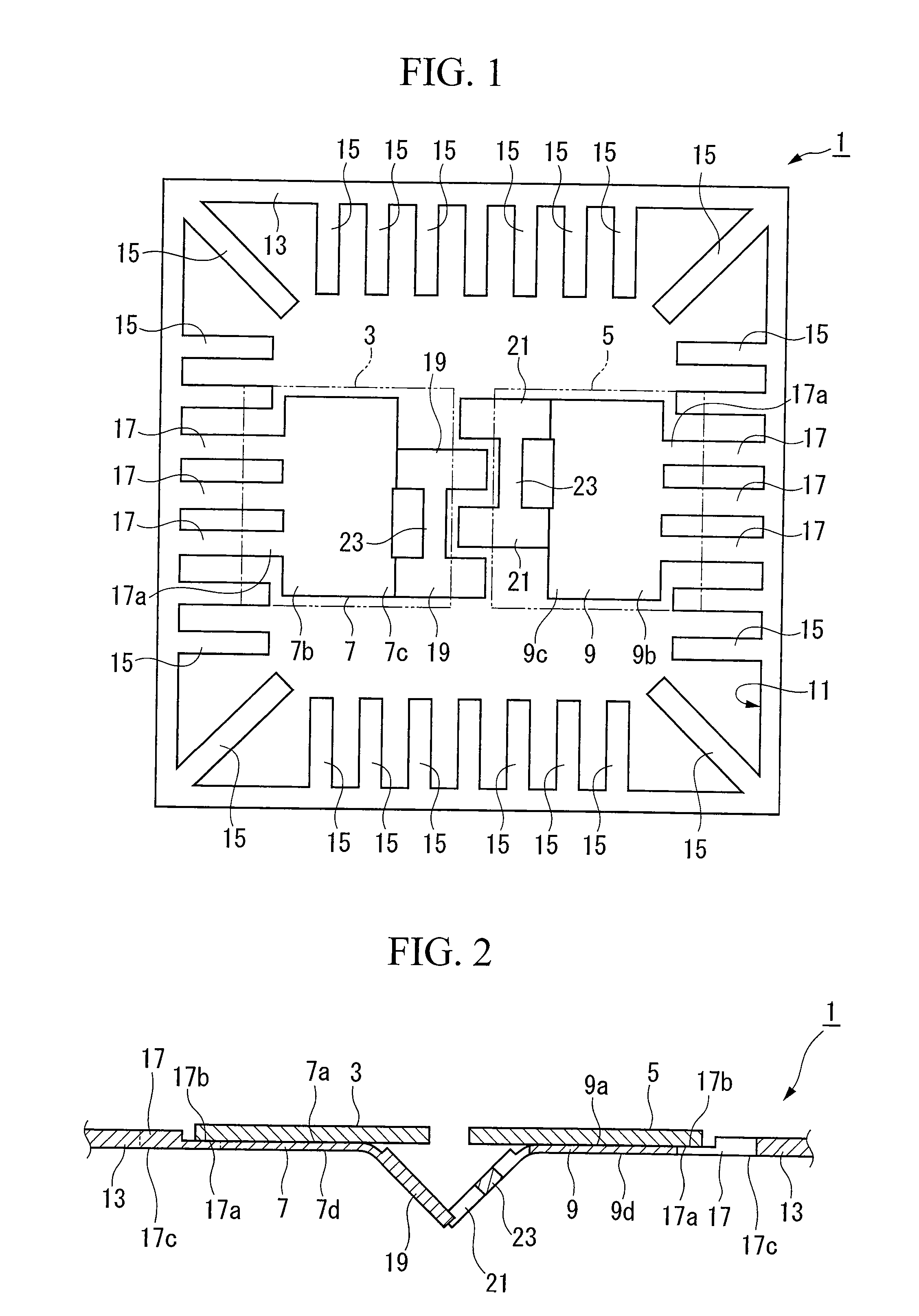
[0082]FIG. 1 to FIG. 7 show a first example of the present invention. The magnetic sensor (physical quantity sensor) according to this example measures the orientation and magnitude of an external magnetic field using the two mutually inclined magnetic sensor chips. This magnetic sensor is produced using a lead frame which is formed by performing a pressing process and an etching process on a metallic plate made from a thin-plate copper material, or the like.

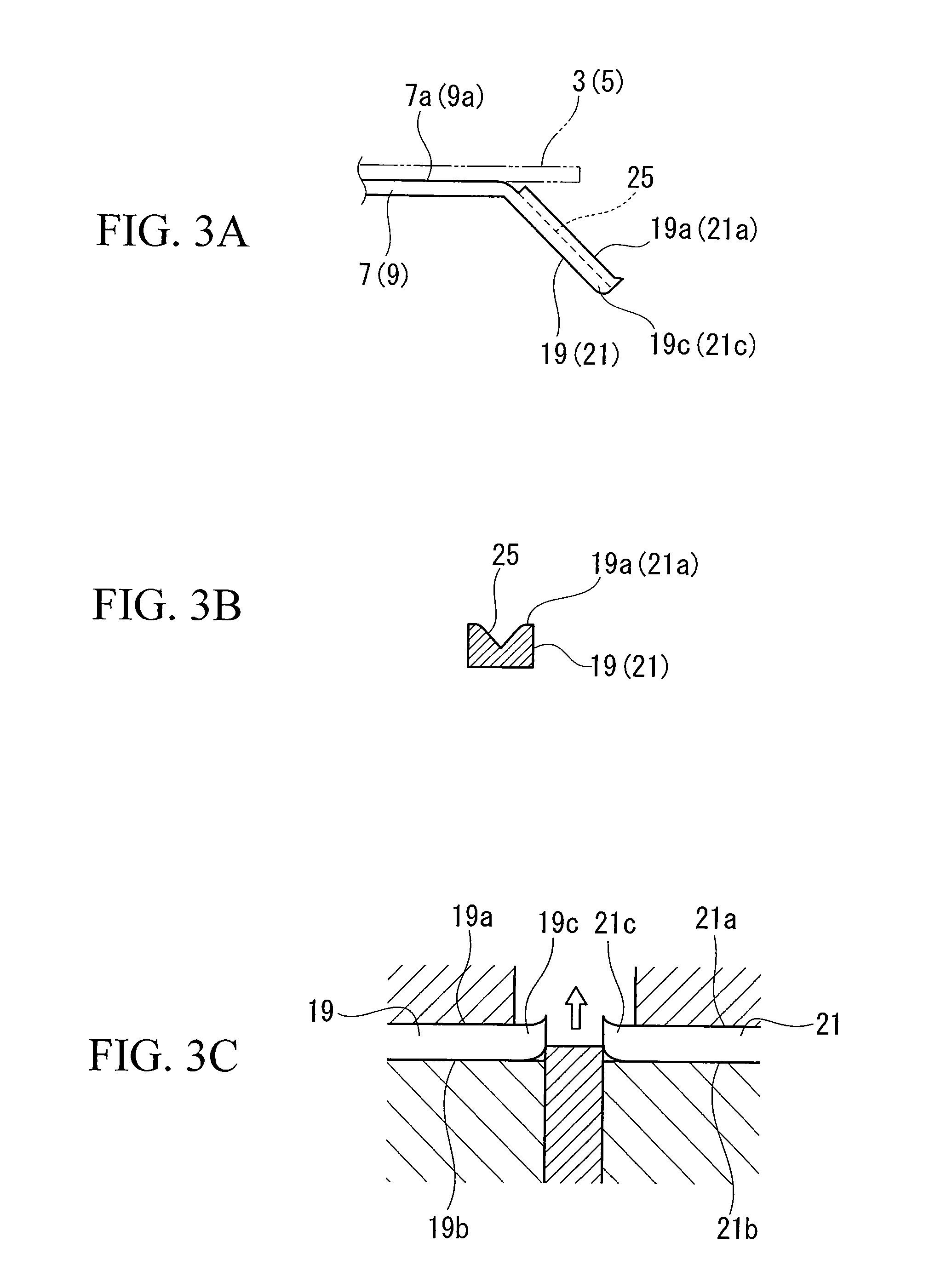
[0083] The lead frame 1 comprises, as shown in FIGS. 1 and 2, two stage portions 7 and 9 for positioning magnetic sensor chips (physical quantity sensor chips) 3 and 5 which have been formed in a plan view rectangular shape, and a frame portion 11 which supports the stage portions 7 and 9. These stage portions 7 and 9, and the frame portion 11 are integrally formed. The frame portion 11 comprises a rectangular frame portion 13, which has been formed in a plan view rectangular frame shape so as to surround the stag...

Example

Second Example

[0121] Next, a second example according to the present invention is explained with reference to FIG. 11 to 13. The lead frame and the magnetic sensor according to this second example differ to the first example with respect to the connection between the frame portion and the stage portion. Here, only the connection section between the frame portion and the stage portion is explained, and the same reference symbols refer to parts the same as the constituent elements of the lead frame 1 and the magnetic sensor 30, and explanation thereof is omitted.

[0122] As shown in FIG. 11 and 12, in this lead frame 2, the stage portions 7 and 9 and the rectangular frame portion 13 are mutually connected as a result of connecting leads (connection portions) 16 which protrude out from the corners of the rectangular frame portion 13. These connecting leads 16 are formed such that they protrude pairwise from the respective stage portions 7 and 9, in locations which become line symmetric...

Example

Third Example

[0159] Next, a third example of the present invention is explained.

[0160] As shown in FIG. 31 and 32, a lead frame 101 comprises; two stage portions 107 and 109 for positioning the magnetic sensor chips (physical quantity sensor chips) 103 and 105, which have been formed in a plate form of a plan view rectangular shape, a frame portion 111 which supports the stage portions 107 and 109, and connection portions 119 and 121 which connect the stage portions 107 and 109 and the frame portion 111. The stage portions 107 and 109, the frame portion 111, and the connection portions 119 and 121 are integrally formed. The frame portion 111 comprises; a rectangular frame portion 113, which is formed in a frame form of a plan view rectangular shape such that it surrounds the stage portions 107 and 109, and a plurality of leads 115 and 117, which protrude from this rectangular frame portion 113 towards the interior. The connection portions 119 and 121 connect the stage portions 107...


PUM


Abstract

A lead frame made from a metallic thin plate, comprising: at least two stage portions on which a physical quantity sensor chip is mounted, and which have an area smaller than a mounting surface of the physical quantity sensor chip; a rectangular frame portion which encloses the stage portions; a plurality of leads including connecting leads which extend in a direction of the stage portion from the frame portion and are positioned on the periphery of the stage portion, and which connect the frame portion and each of the stage portions; and an easily deformed portion formed on the connecting leads which inclines the stage portion by becoming deformed; and the physical quantity sensor chip is mounted by superimposing the mounting surface on the stage portion and a portion of the plurality of leads in the direction of thickness of the frame portion.

Description

TECHNICAL FIELD [0001] This invention relates to a physical quantity sensor which determines the azimuth and the orientation of physical quantities, such as magnetism, gravity, and the like, and a lead frame used for the same. [0002] Priority is claimed on Japanese Patent Application No. 2004-290472 filed Oct. 1, 2004, Japanese Patent Application No. 2004-296370 filed Oct. 8, 2004, and Japanese Patent Application No. 2005-87621 filed Mar. 25, 2005, the contents of which are incorporated herein by reference. BACKGROUND ART [0003] In recent years, amongst portable terminal devices, such as mobile telephones, devices possessing a GPS (Global Positioning System) function, which displays the position information of users, have emerged. In addition to this GPS function, by providing a function which accurately detects terrestrial magnetism, and a function which detects acceleration, detection of the azimuth and the orientation in three-dimensional space, or the movement direction, of the ...

Claims


Application Information

Patent Timeline
IPC IPC(8): G01L9/16
CPCH01L21/4842H01L23/49548H01L2224/73265H01L2224/32245H01L24/49H01L24/48H01L2224/49171H01L2224/48247H01L2224/48137H01L2224/48091H01L23/49575H01L2924/00014H01L2924/00H01L2224/451H01L24/45H01L2924/181H01L2224/05554H01L2224/48257H01L2224/05599H01L2924/00012
Inventor SHIRASAKA, KENICHI
Owner YAMAHA CORP
Why Eureka
Try Eureka