

Connector, optical transmission module and optical-electrical transmission module
a technology of optical transmission module and connector, applied in the direction of optical elements, coupling device connections, instruments, etc., can solve the problems of not being easy to make the size smaller and the height shorter, and achieve the effect of shortening the heigh
- Summary
- Abstract
- Description
- Claims
- Application Information
AI Technical Summary
Benefits of technology
Problems solved by technology
Method used
Image

Examples
first embodiment
[0066]A plug constituting a connector formed on one end of the film cable is described in the first embodiment.
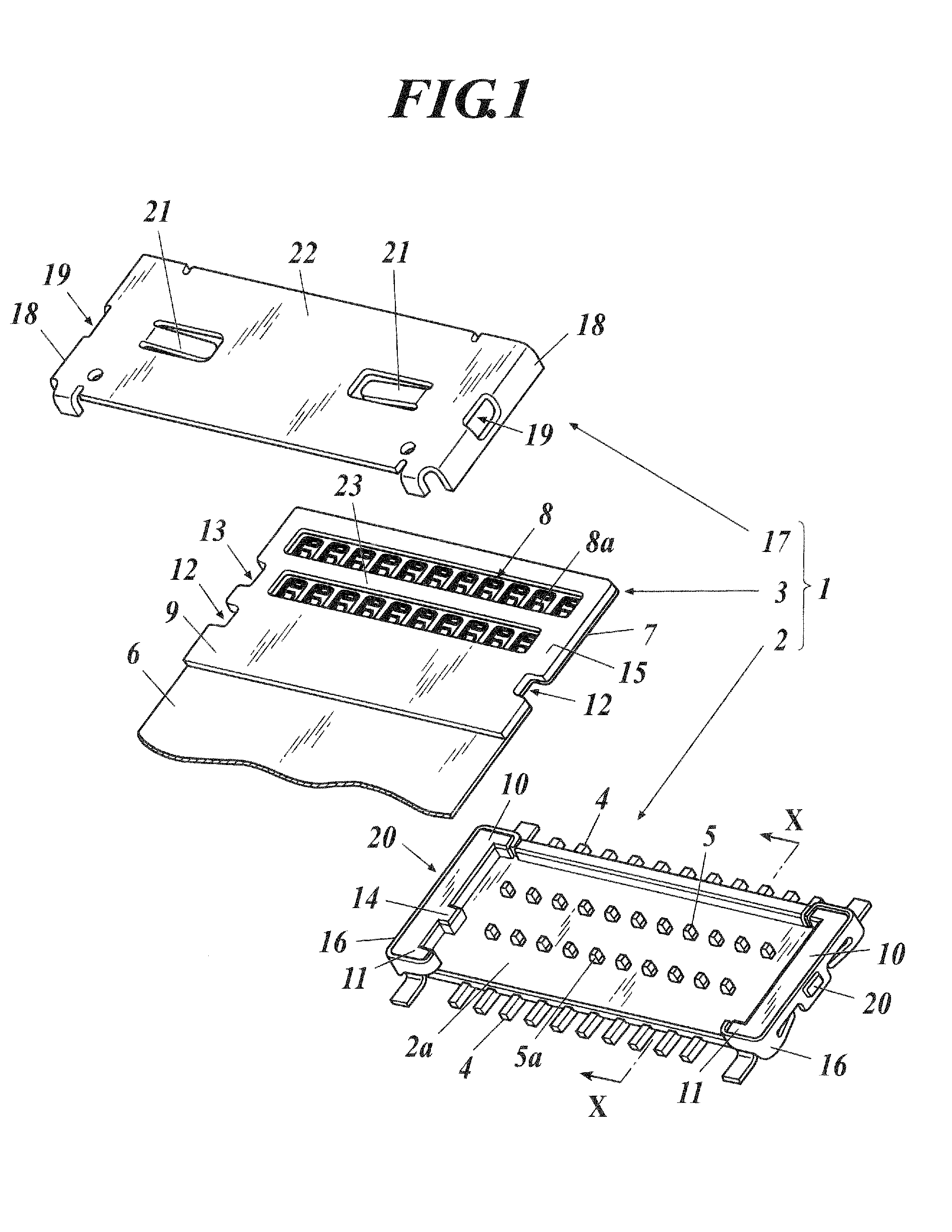
[0067]As shown in FIG. 1, the connector 1 of the present embodiment includes a receptacle 2 provided on a substrate (not shown) and a plug 3 connected to the receptacle 2.
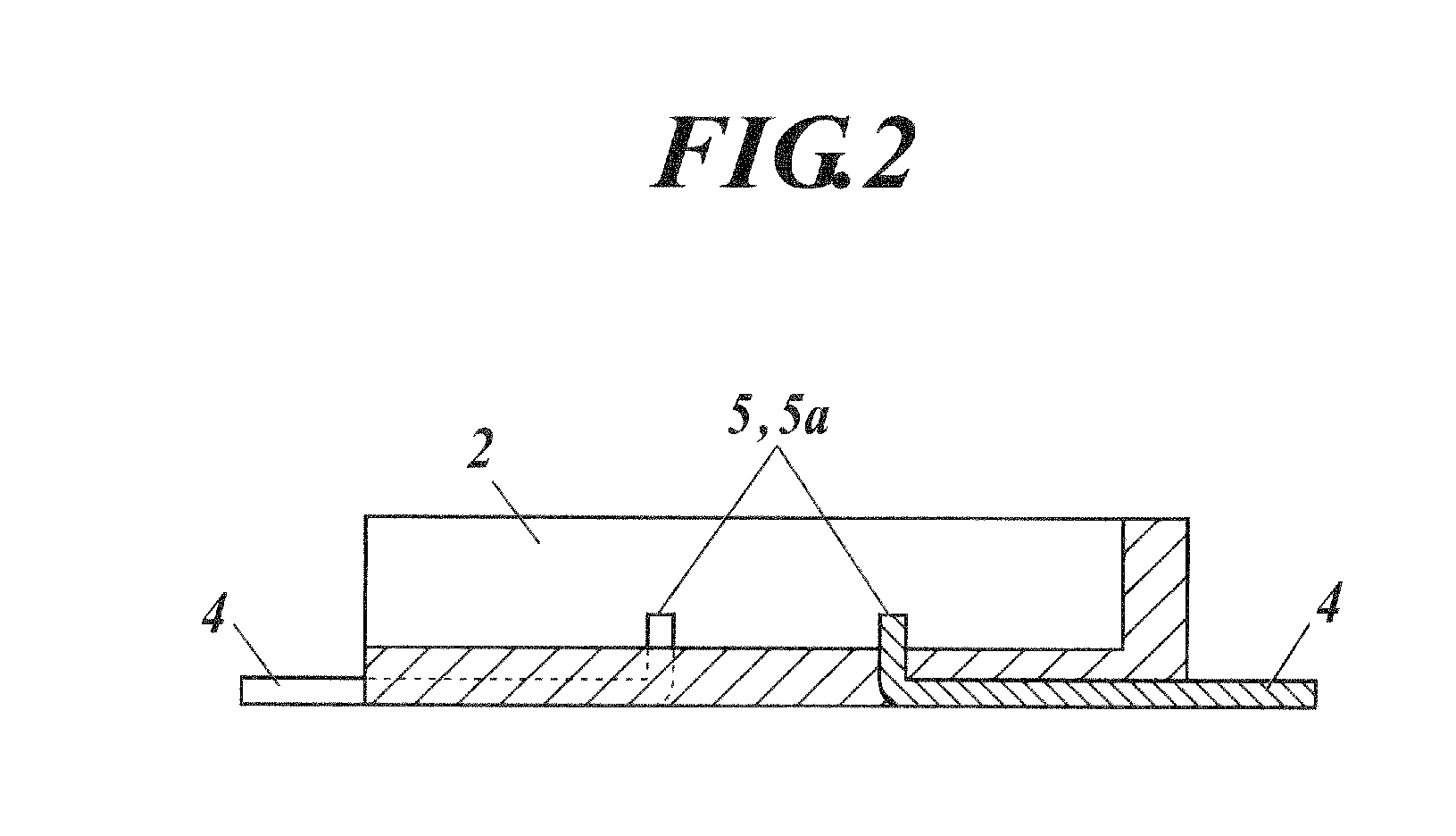
[0068]The specification describes the embodiment using the terms up, down, horizontal direction, etc. based on when the base section 2a of the receptacle 2 extends in a horizontal direction and point 5a of a projecting terminal 5 is placed to project upward as shown in FIG. 1. However, the terms up, down, horizontal direction, etc. are to describe a relative relation of position of each member. In other words, needless to say, for example, when the receptacle 2 is mounted downward and the point 5a of the projecting terminal 5 is placed projecting downward, the up and down described below is reversed, and when the receptacle 2 is mounted sideways and the point 5a of the projecting terminal 5 is placed proje...
second embodiment
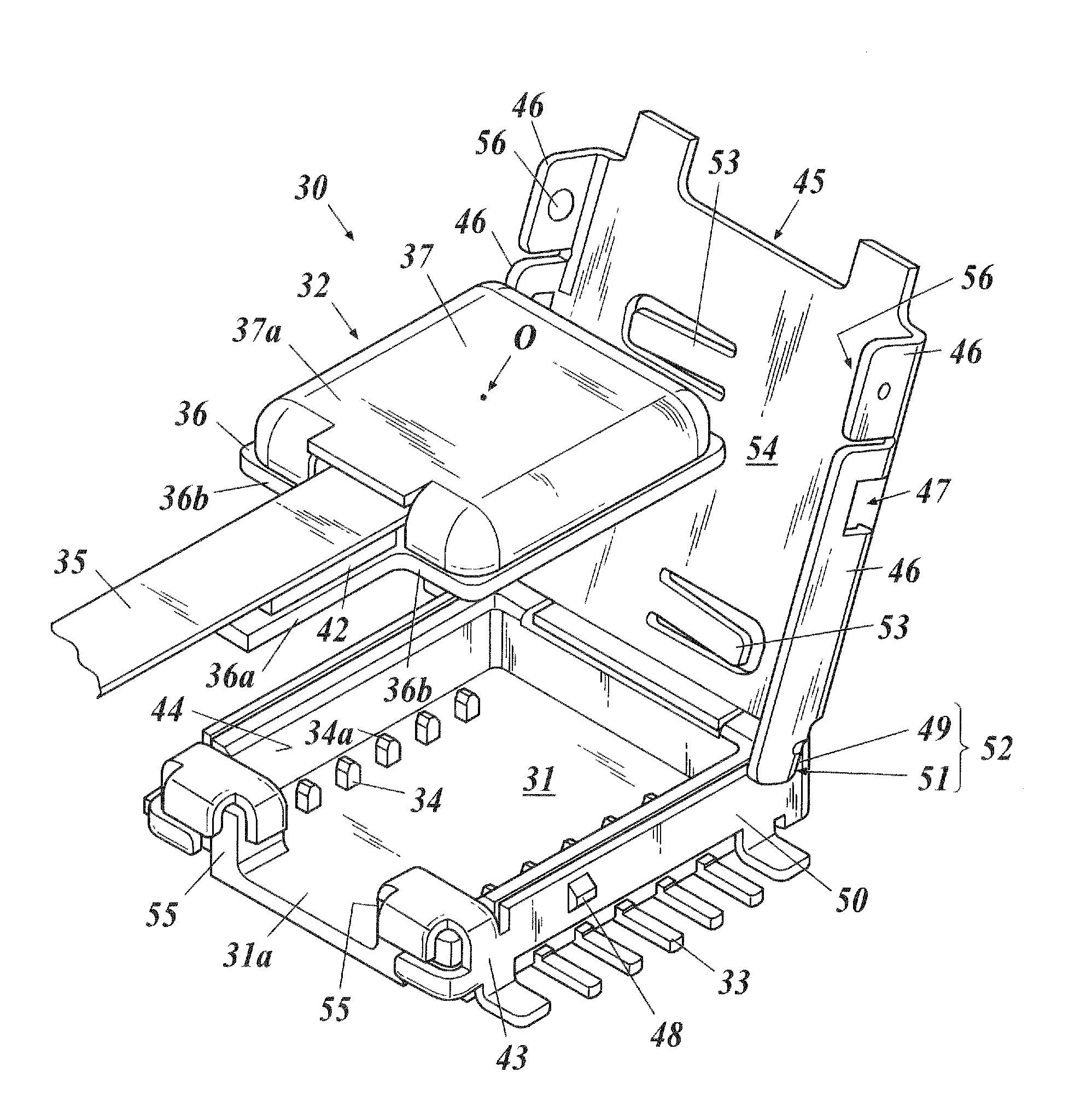
[0119]The second embodiment describes an example where a plug composing a connector is formed on one end of an optical transmission waveguide film and the plug mutually converts an electrical signal and optical signal to send and receive the signals. As described above, in the present embodiment, an optical transmission module is formed by the connector. Therefore, below, the connector 30 can be read as the optical transmission module 30.
[0120]As shown in FIG. 12, the connector 30 of the present invention includes a receptacle 31 provided on a substrate (not shown) and a plug 32 connected to the receptacle 31.
[0121]On the receptacle 31, a projecting terminal 34 is provided electrically connected to the external terminal 33. In the present embodiment also, similar to the projecting terminal 5 shown in FIG. 2 and FIG. 3A of the first embodiment, the projecting terminal 34 is formed integrated with the external terminal 33 in a substantial L-shape, and is formed by insert molding so th...
third embodiment
[0150]The third embodiment describes an example where a plug composing a connector is formed on one end of the optical transmission waveguide film, the plug mutually converts the electrical signal and the optical signal to send and receive the signals, and the plug includes the FPC for electrical signal transmission. As described above, according to the present embodiment, not only the optical signal but also the electrical signal can be transmitted by the connector and an optical-electrical transmission module is formed. Therefore, below, the connector 60 can be read as the optical-electrical transmission module 60.
[0151]The connector 60 (optical-electrical transmission module 60) of the present embodiment and the connector 30 (optical transmission module 30) of the second embodiment have almost the same structure and the operation and effect are also the same, therefore, only points different from the connector 30 (optical transmission module 30) of the second embodiment will be d...
PUM
 Abstract
Description
Claims
Application Information