Automatic retractable syringe

Inactive Publication Date: 2009-08-20
FUJIFILM CORP +1
View PDF7 Cites 19 Cited by
  • Summary
  • Abstract
  • Description
  • Claims
  • Application Information

AI Technical Summary

Benefits of technology

[0018]According to the automatic retractable syringe of the present invention, an unlimited amount of air or water can be supplied in an easy and consecutive manner by repeating the pressing operation.
[0019]In addition, the automatic retractable syringe for an endoscope has an advantage capable of providing a si

Problems solved by technology

However, as described above, the conventional endoscope apparatus requires the air supply/water supply pump (device) 8 to supply air and water, and thus has a problem in that it is difficult to use the endoscope in a place other than a facility provid

Method used


Image

  • Automatic retractable syringe
  • Automatic retractable syringe
  • Automatic retractable syringe

Examples


Embodiment Construction

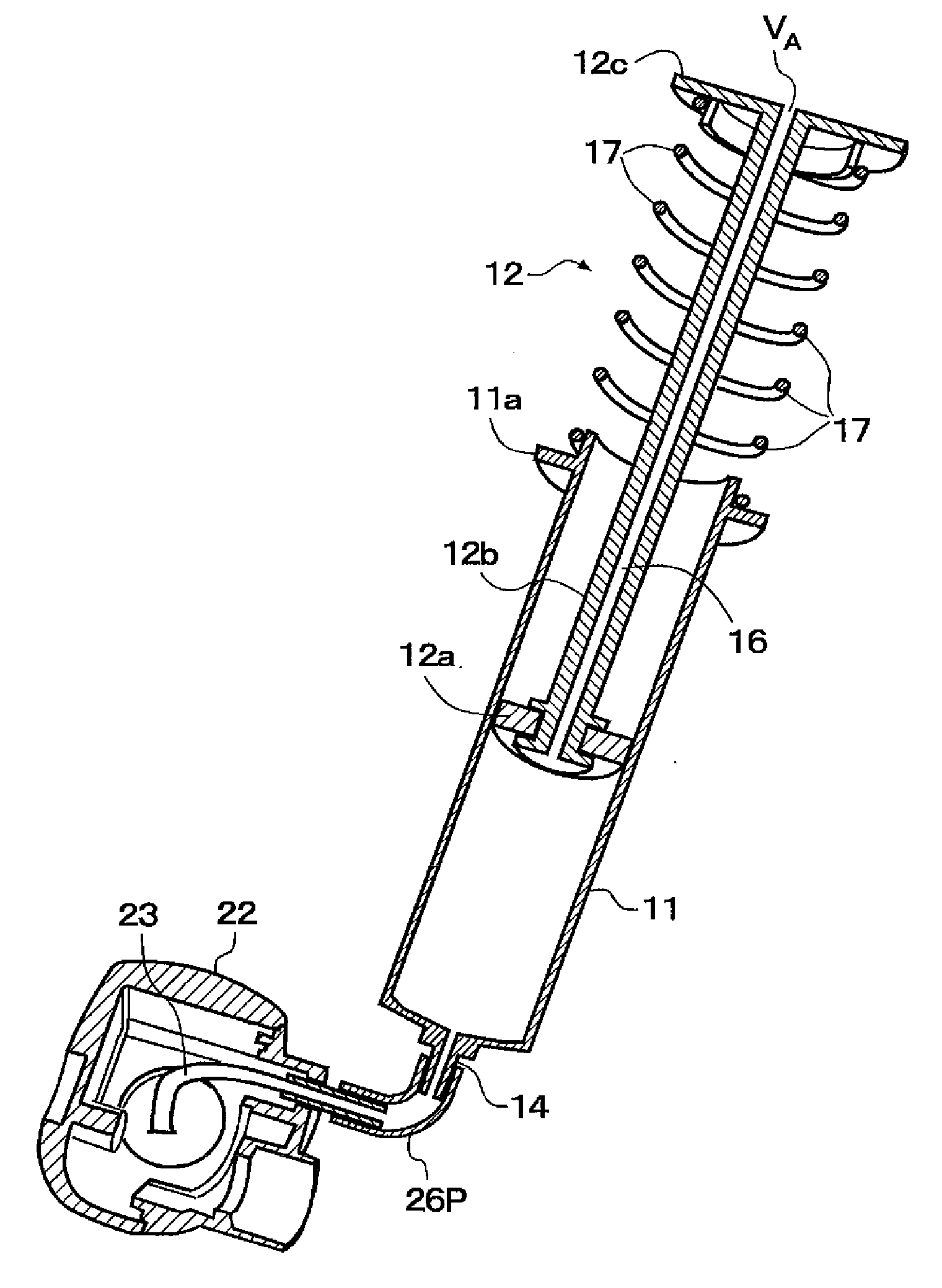
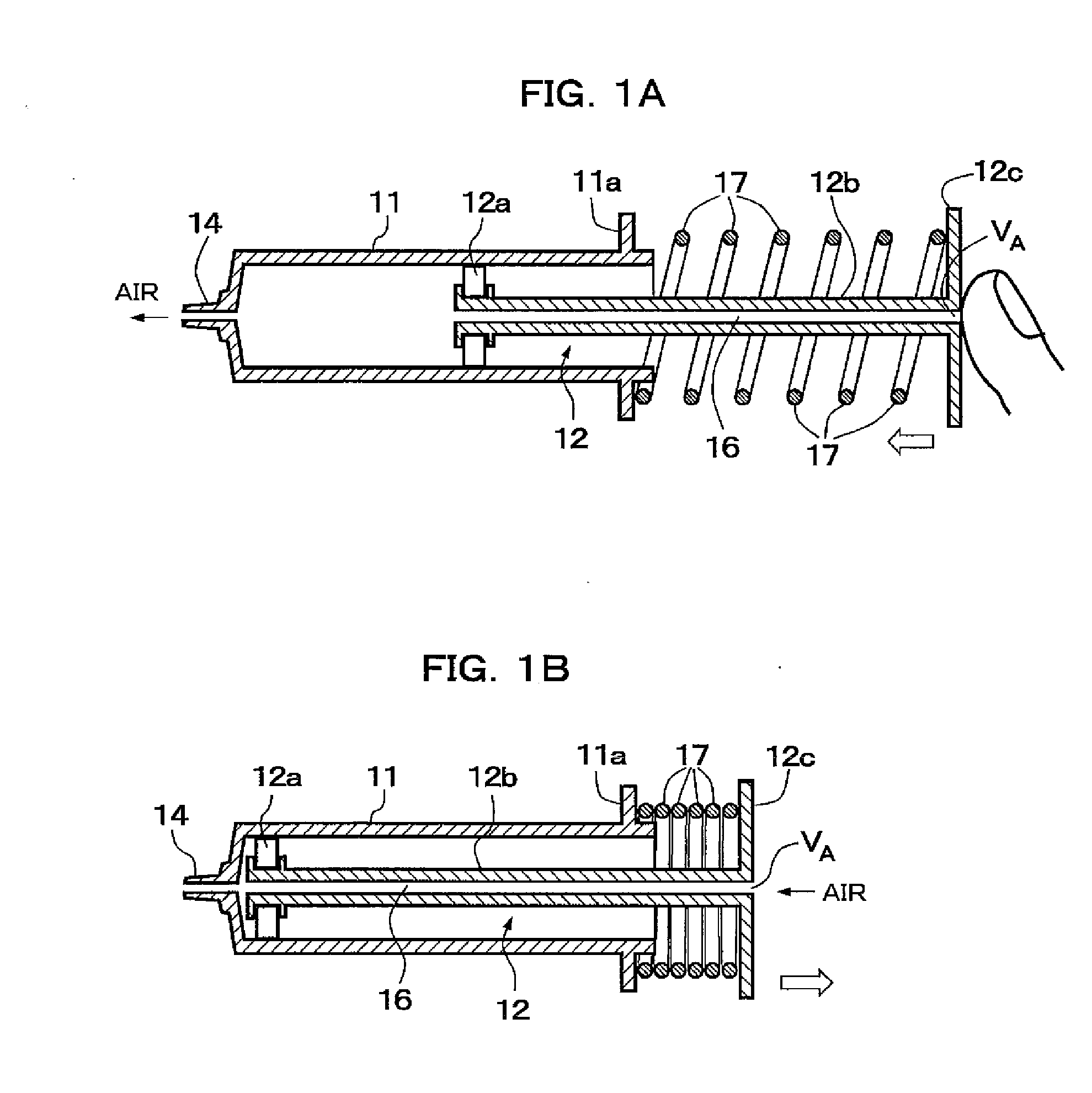
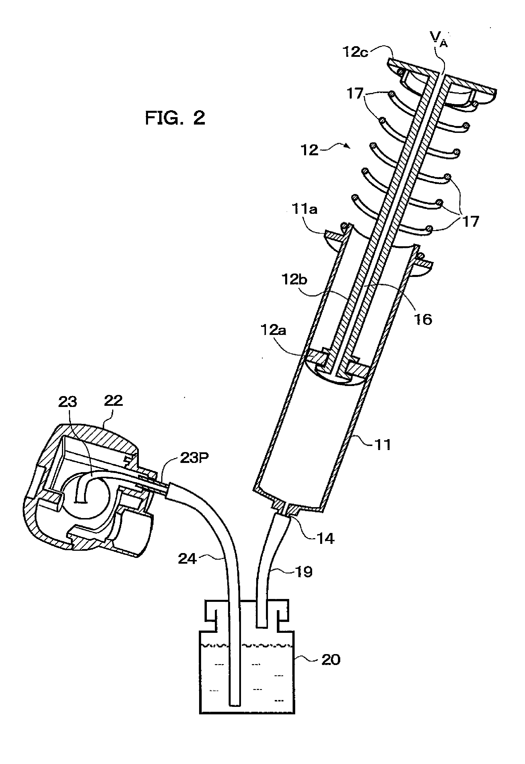
[0026]FIG. 1 illustrates a configuration of an automatic retractable syringe in accordance with an embodiment of the present invention. FIGS. 2 to 4 illustrate a configuration of an automatic retractable syringe for an endoscope in accordance with the embodiment. First, as shown in FIG. 1, the syringe of the present embodiment has a cylindrical tubular body 11 and a piston body (slider) 12. The tubular body 11 includes a syringe opening (injection opening) 14 on a front end surface thereof.

[0027]On the other hand, the piston body 12 includes a discoid piston portion (sliding portion) 12a with a predetermined thickness which slides (reciprocates) in close contact with an inner surface of the tubular body 11, a cylindrical rod-shaped shaft portion 12b which supports the piston portion 12a and whose external diameter is smaller than the internal diameter of the tubular body 11, and a discoid pressing portion 12c which is disposed at a rear side of the shaft portion 12b so as to move ba...


PUM


Abstract

An automatic retractable syringe includes a tubular body on which a syringe opening is provided; a piston body in whose pressing portion a vent hole VA is formed and in whose shaft portion a vent passage passing from the vent hole VA through inside to the front end portion is formed; and a spring which returns the pressed piston body to its original position. When the pressing portion is pressed by a thumb or other finger plugging the vent hole VA to move the piston body forward, air is supplied from the syringe opening. Subsequently, when the thumb or other finger is released, air flows into the tubular body through the vent hole VA and the vent passage, and the piston body automatically returns to its original position by the spring. Therefore, air can be consecutively supplied by repeatedly pressing the pressing portion.

Description

BACKGROUND OF THE INVENTION[0001]The disclosure of Japanese Patent Application No. 2008-035847, filed on Feb. 18, 2008, including its specification, claims and drawings, is incorporated herein by reference in its entirety.[0002]1. Field of the Invention[0003]The present invention relates to an automatic retractable syringe, and more particularly to a configuration of a syringe which is used to supply air or water using an air supply / water supply tube provided particularly in an endoscope or the like and can be carried as an air supply / water supply device.[0004]2. Description of the Related Art[0005]FIG. 5 illustrates a configuration of a conventional endoscope apparatus (see Japanese Patent Laid-Open No. 2003-135391). The endoscope (scope) has, for example, a front end portion 1A provided with a solid state image pickup element, an operation portion 1B provided through a curved portion, and the like. This endoscope includes an air supply / water supply tube 3a for cleaning an observat...

Claims


Application Information

Patent Timeline
IPC IPC(8): A61B1/12
CPCA61B1/015F04B33/00A61M5/3148
Inventor YAMANE, KENJI
Owner FUJIFILM CORP
Why Eureka
Try Eureka