This helps you quickly interpret patents by identifying the three key elements:
Problems solved by technology
Method used
Benefits of technology
Benefits of technology
[0007]In view of the above, an object of one embodiment of the present invention is to increase the range of distance (between a display screen and the eye of a viewer) with which the viewer can see 3D images by the naked eye.
[0011]According to one embodiment of the present invention, the range of distance with which a viewer can see 3D images by the naked eye can be increased. A highly convenient display device can be provided as a result.
Problems solved by technology
However, in order to display 3D images by a parallaxbarrier method, a specific distance is needed between a display screen and the eye of a viewer.
Method used
Image
Click on the blue label to locate the original text in one second.
Reading with bidirectional positioning of images and text.
Examples
embodiment 1
[0025]First, a display device according to one embodiment of the present invention will be described with reference to FIGS. 1A and 1B, FIGS. 2A to 2C, and FIGS. 3A and 3B.
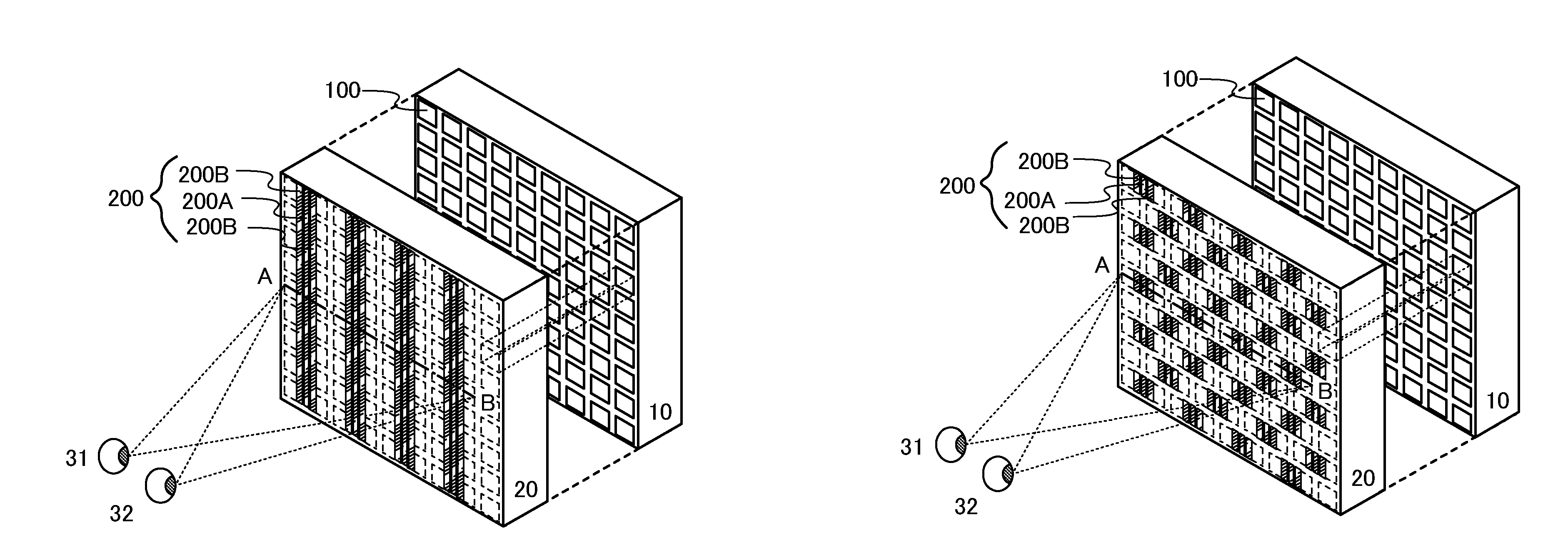
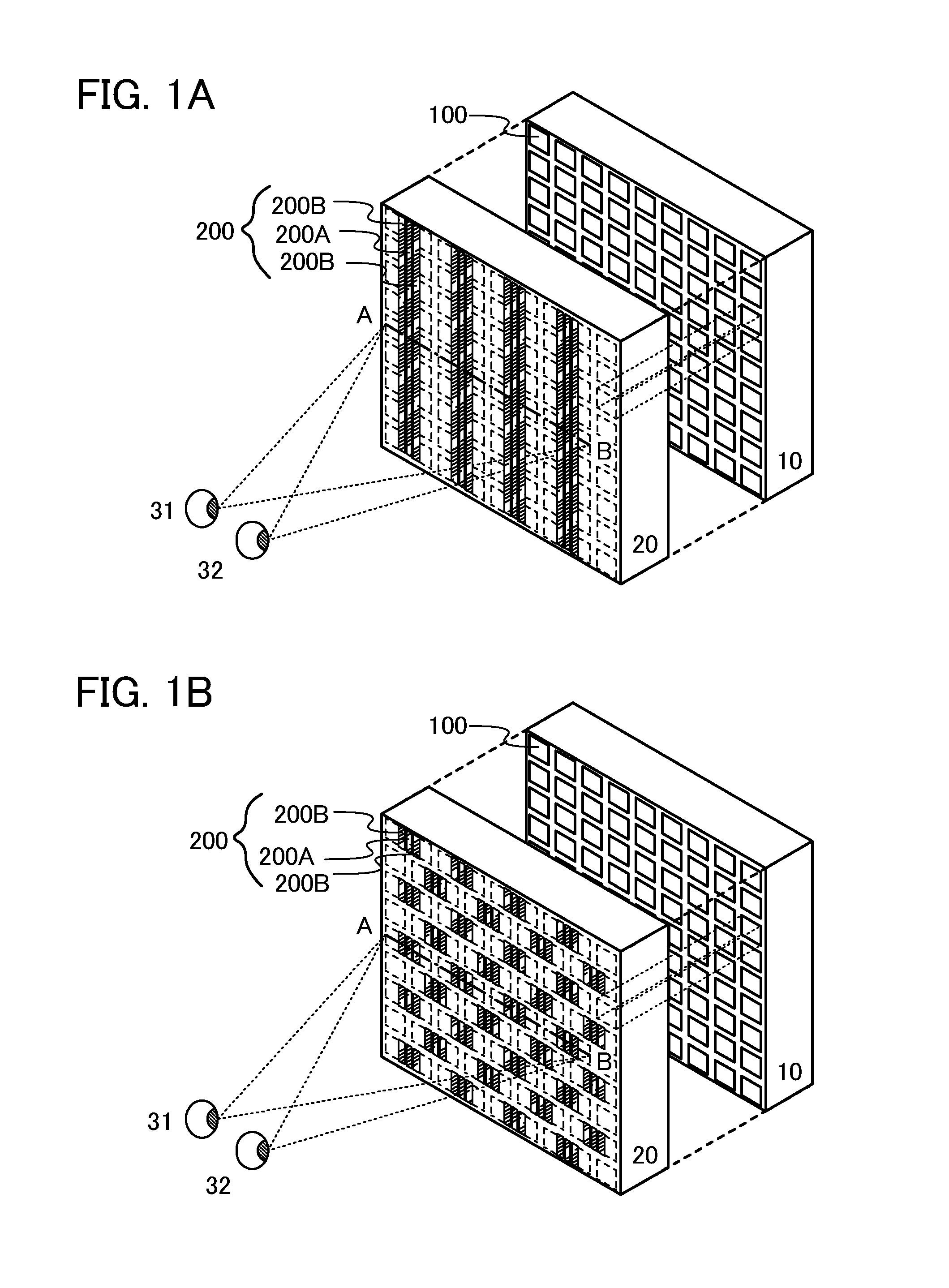
[0026]FIGS. 1A and 1B are schematic diagrams each illustrating a display device according to one embodiment of the present invention. The display device illustrated in FIG. 1A includes a display panel 10 in which a plurality of pixels 100 are arranged in matrix, and a shutter panel 20 in which first liquid crystal elements 200A and second liquid crystal elements 200B are adjacent to each other and arranged in a stripe pattern. The display device illustrated in FIG. 1B includes a display panel 10 in which a plurality of pixels 100 are arranged in matrix, and a shutter panel 20 in which first liquid crystal elements 200A and second liquid crystal elements 200B are adjacent to each other and arranged in matrix. FIGS. 1A and 1B illustrate a left eye 31 and a right eye 32 of a viewer in order to show a state of the vie...
embodiment 2
[0048]In this embodiment, specific examples of a shutter panel in the display device according to one embodiment of the present invention will be described with reference to FIGS. 4A1, 4A2, 4B1, 4B2, 4C1, and 4C2 and FIGS. 5A and 5B. The shutter panel described in this embodiment is a specific example of the shutter panel 20 in Embodiment 1.
[0049]The shutter panel is constituted by a plurality of optical elements whose state is switched between a light-shielding state and a light-transmitting state. As the optical element, it is preferable to use a liquid crystal element in which liquid crystal is placed between a pair of electrodes. By application of voltage to the liquid crystal element, alignment of the liquid crystal is controlled to selectively control the state (a light-shielding state or a light-transmitting state) of the liquid crystal element.
[0050]FIGS. 4A1 and 4A2 illustrate a shutter panel 500a. FIG. 4A1 is a plan view of the shutter panel 500a. FIG. 4A2 is a cross-secti...
embodiment 3
[0069]In this embodiment, examples of the structure of a display panel applicable to the display panel in Embodiment 1 will be described with reference to FIGS. 6A and 6B and FIGS. 7A and 7B.
[0070]As a display element provided in the display panel, a light-emitting element (also referred to as a light-emitting display element) or a liquid crystal element (also referred to as a liquid crystal display element) can be used. A light-emitting element includes, in its category, an element whose luminance is controlled by current or voltage, and specifically includes an inorganic electroluminescent (EL) element, an organic EL element, and the like.
[0071]FIGS. 6A and 6B illustrate an example of the structure of a display panel in which an organic EL element is used as a display element. FIG. 6A is a plan view of the display panel. FIG. 6B is a cross-sectional view along A-B and C-D in FIG. 6A. An element substrate 410 is fixed to a sealing substrate 404 with a sealant 405, and includes driv...
PUM
Abstract
A display device includes a display panel and a shutter panel that is provided on the viewer side of the display panel and includes a first liquid crystal element and a second liquid crystal element adjacent to each other. In a first display state, a first light-shielding region and a first light-transmitting region are formed in the shutter panel by the first liquid crystal element, and light from the display panel is emitted through the first light-transmitting region. In a second display state, a second light-shielding region larger than the first light-shielding region and a second light-transmitting region smaller than the first light-transmitting region are formed in the shutter panel by the first liquid crystal element and the second liquid crystal element, and light from the display panel is emitted through the second light-transmitting region.
Description
TECHNICAL FIELD[0001]The present invention relates to display devices and particularly relates to a display device capable of displaying three-dimensional (3D) images.BACKGROUND ART[0002]Display devices are widely used, ranging from large display devices such as television devices to small display devices such as mobile phones. High value-added products will be needed and are being developed. In recent years, display devices that can display 3D images have been developed in order to display more realistic images.[0003]As methods for displaying 3D images, there are a method using glasses for separating an image seen with a left eye and an image seen with a right eye (also referred to as stereoscopy), and autostereoscopy by which 3D images can be seen by the naked eye by addition of a structure for separating an image seen with a left eye and an image seen with a right eye in a display portion. It is not necessary to prepare glasses to see autostereoscopic 3D images, which offers a hi...
Claims
Application Information
Patent Timeline
Application Date:The date an application was filed.
Publication Date:The date a patent or application was officially published.
First Publication Date:The earliest publication date of a patent with the same application number.
Issue Date:Publication date of the patent grant document.
PCT Entry Date:The Entry date of PCT National Phase.
Estimated Expiry Date:The statutory expiry date of a patent right according to the Patent Law, and it is the longest term of protection that the patent right can achieve without the termination of the patent right due to other reasons(Term extension factor has been taken into account ).
Invalid Date:Actual expiry date is based on effective date or publication date of legal transaction data of invalid patent.

