Method, system and computer program product for end to end error checking in ethernet

a technology of error checking and ethernet protocol, applied in the field of ethernet, can solve problems such as problems in the implementation of data center systems

Inactive Publication Date: 2009-08-20
IBM CORP
View PDF16 Cites 8 Cited by
  • Summary
  • Abstract
  • Description
  • Claims
  • Application Information

AI Technical Summary

Problems solved by technology

However, the use of many different protocol standards in data centers leads to problems in implementing data center systems.

Method used


Image

  • Method, system and computer program product for end to end error checking in ethernet
  • Method, system and computer program product for end to end error checking in ethernet
  • Method, system and computer program product for end to end error checking in ethernet

Examples


Embodiment Construction

[0014]An exemplary embodiment of the present invention provides improved error checking in an Ethernet protocol.

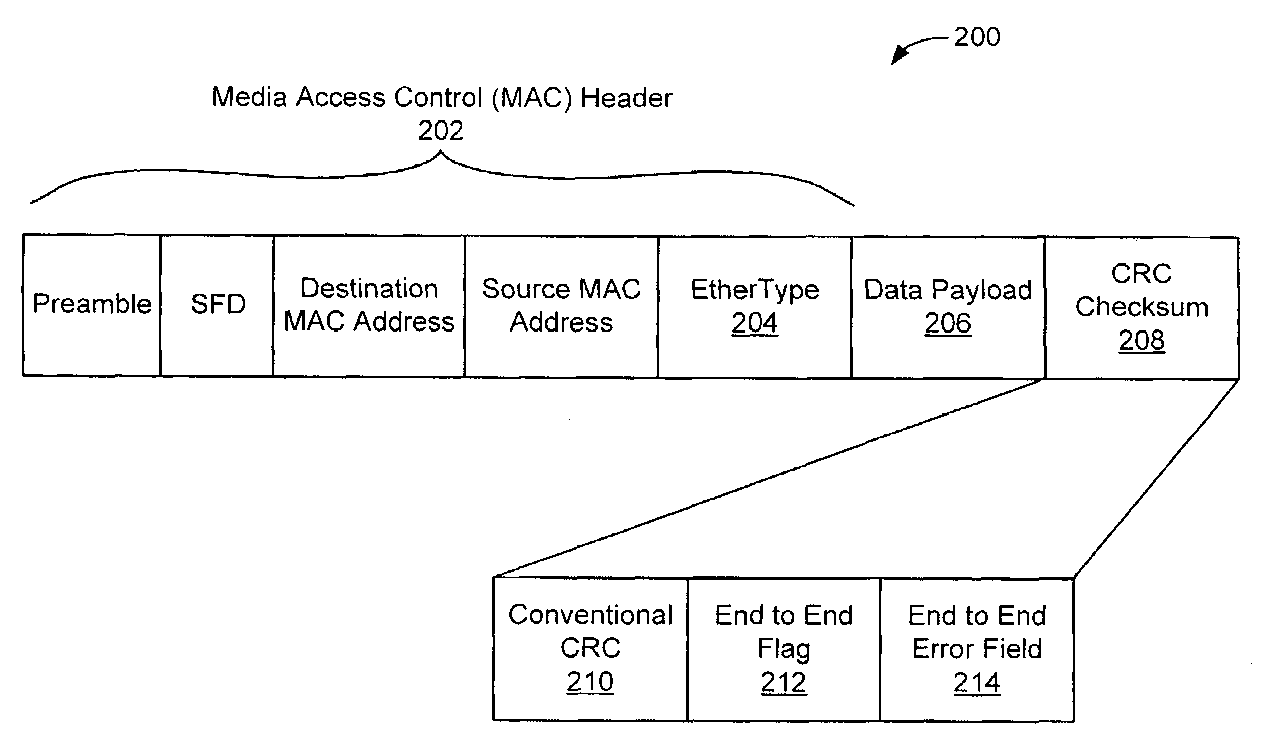
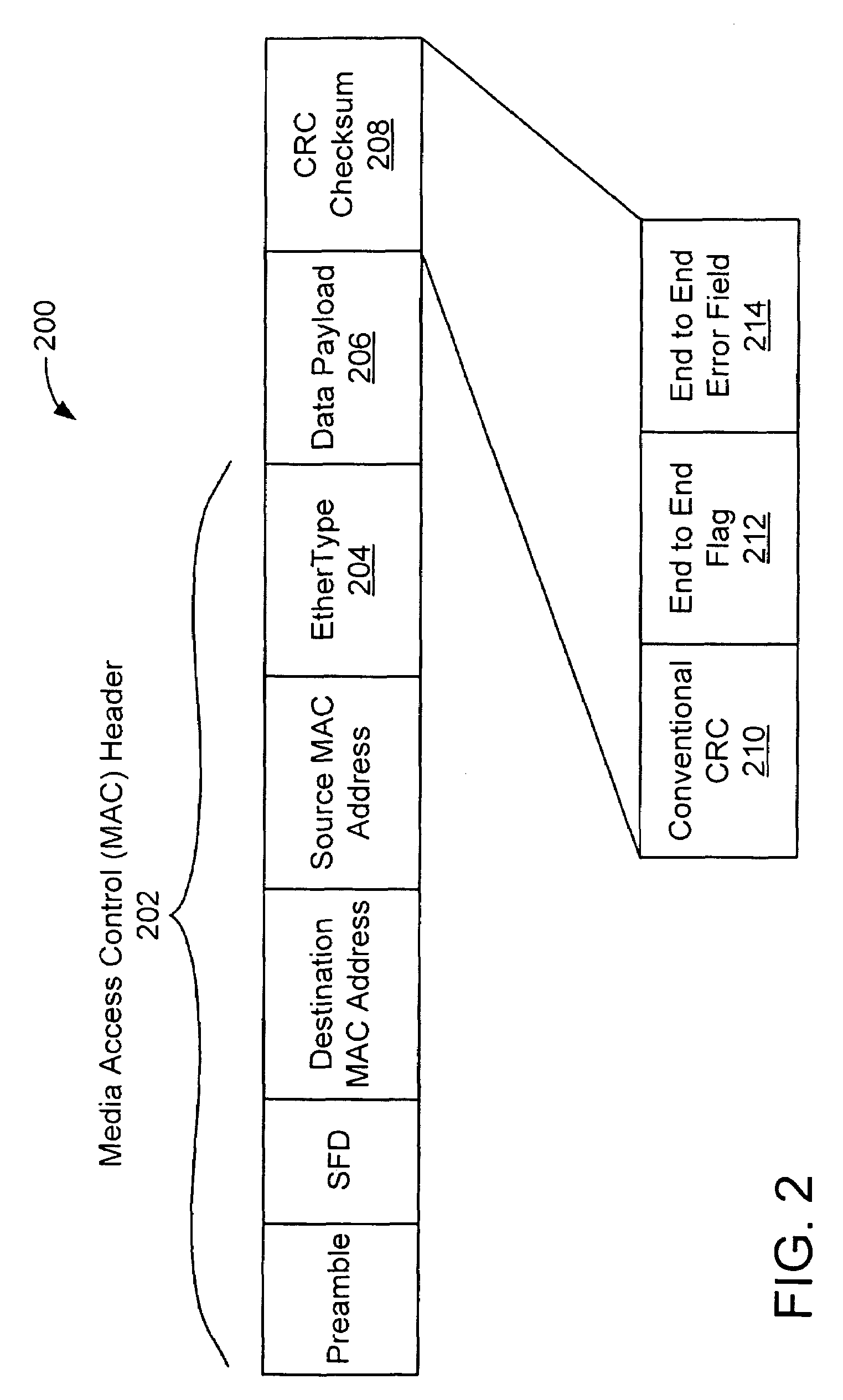
[0015]As data packets are transmitted and received through a network, bit errors often occur in the data packets. The Ethernet (type II) protocol (as defined in IEEE 802.3) provides a frame check sequence (FCS) field that checks for errors. As a data packet is received and transmitted by switching nodes in a network, each node implements error detection to avoid wasting bandwidth by transmitting erroneous frames. When a node detects and error, it discards the frame rather than forwarding on to the next node. A cyclic redundancy check (CRC) is used for error detection.

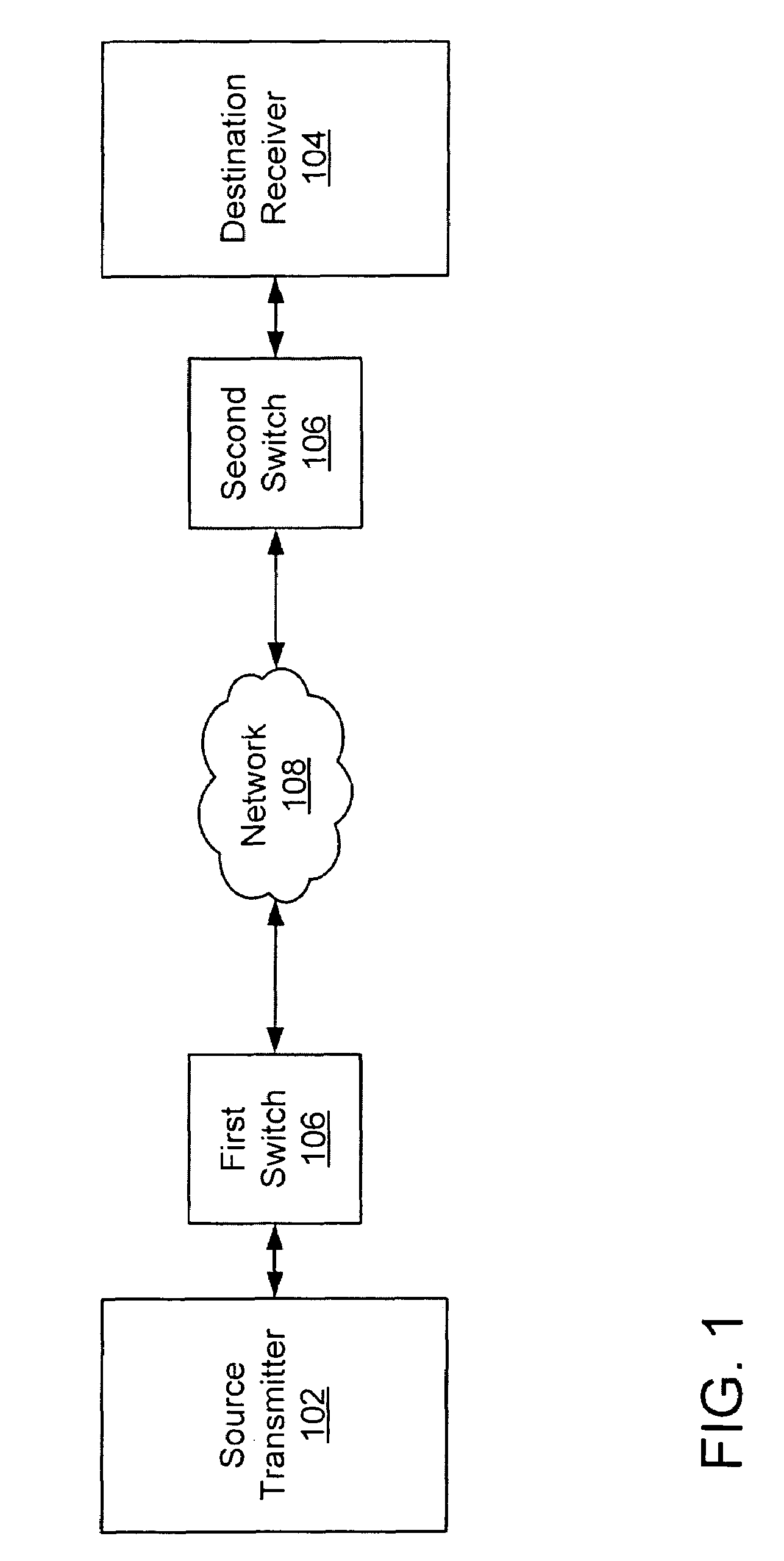
[0016]Data packets sent via the Ethernet protocol are commonly switched at a data link layer (layer 2 of the Open Systems Interconnect (OSI) model) that uses a Media Access Control (MAC) address for switching. As data packets are received and transmitted at switching nodes, frames with errors are detected usin...


PUM


Abstract

A method for network protocol error correction comprising, generating a data packet including a cycle redundancy check (CRC) field, an end to end error field that remains unchanged as the data packet is sent over a network, for use in performing error detection in one or more field of the data packet, and a flag field associated with the end to end field to indicate that the end to end error field contains error correction data, and sending the data packet over a network via an Ethernet protocol.

Description

BACKGROUND OF THE INVENTION[0001]This invention relates generally to Ethernet, and more particularly to providing error checking in an Ethernet protocol.[0002]Ethernet is a frame-based networking technology for local area networks. The Ethernet protocols are standardized in, for example, IEEE 802.3. Data is sent via Ethernet protocols over networks via switches, bridges, and hubs that are hardware devices designed to transmit data with the Ethernet protocol.[0003]Data Center Ethernet (DCE) is a modification of the Ethernet standard that may allow Ethernet to be a preferred protocol for all types of data center network traffic. This may also be known by other names, such as, for example, low latency Ethernet, next generation Ethernet, or Fibre Channel over Ethernet. Many data centers use different protocols for transmitting data that offer features not available in the Ethernet protocol, such as more robust error checking. However, the use of many different protocol standards in data...

Claims


Application Information

Patent Timeline
Patent Type & Authority Applications(United States)
IPC IPC(8): G06F11/10
CPCH04L1/004H04L1/0061
Inventor DECUSATIS, CASIMERGREGG, THOMAS A.
Owner IBM CORP
Why Eureka
Try Eureka