Memory system and method using partial ECC to achieve low power refresh and fast access to data

Active Publication Date: 2008-04-17
MICRON TECH INC
View PDF98 Cites 62 Cited by
  • Summary
  • Abstract
  • Description
  • Claims
  • Application Information

AI Technical Summary

Benefits of technology

[0012]An error checking and correcting semiconductor device and method performs a reduced power refresh using ECC techniques only for memory cells that store infrequently accessed data. The memory cells that store this infrequently accessed data may be refreshed at a relatively low rate, thereby substantially reducing the power consumed by the semiconductor device. Memory cells that store frequently accessed data may be refreshed at a normal rate that does not require ECC techniques to ensure data integrity. As a result, this frequently accessed data is immediately available without the need to enter and exit the reduced power refresh mode. In the event most of the data stored in the semiconductor d

Problems solved by technology

The usefulness of portable electronic devices, such as notebook computers, is limited by the limited length of time batteries are capable of powering the device before needing to be recharged.
For example, electronic devices such a notebook computer, typically include 
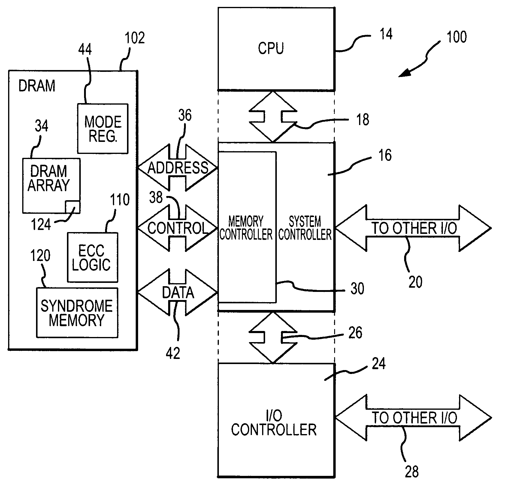
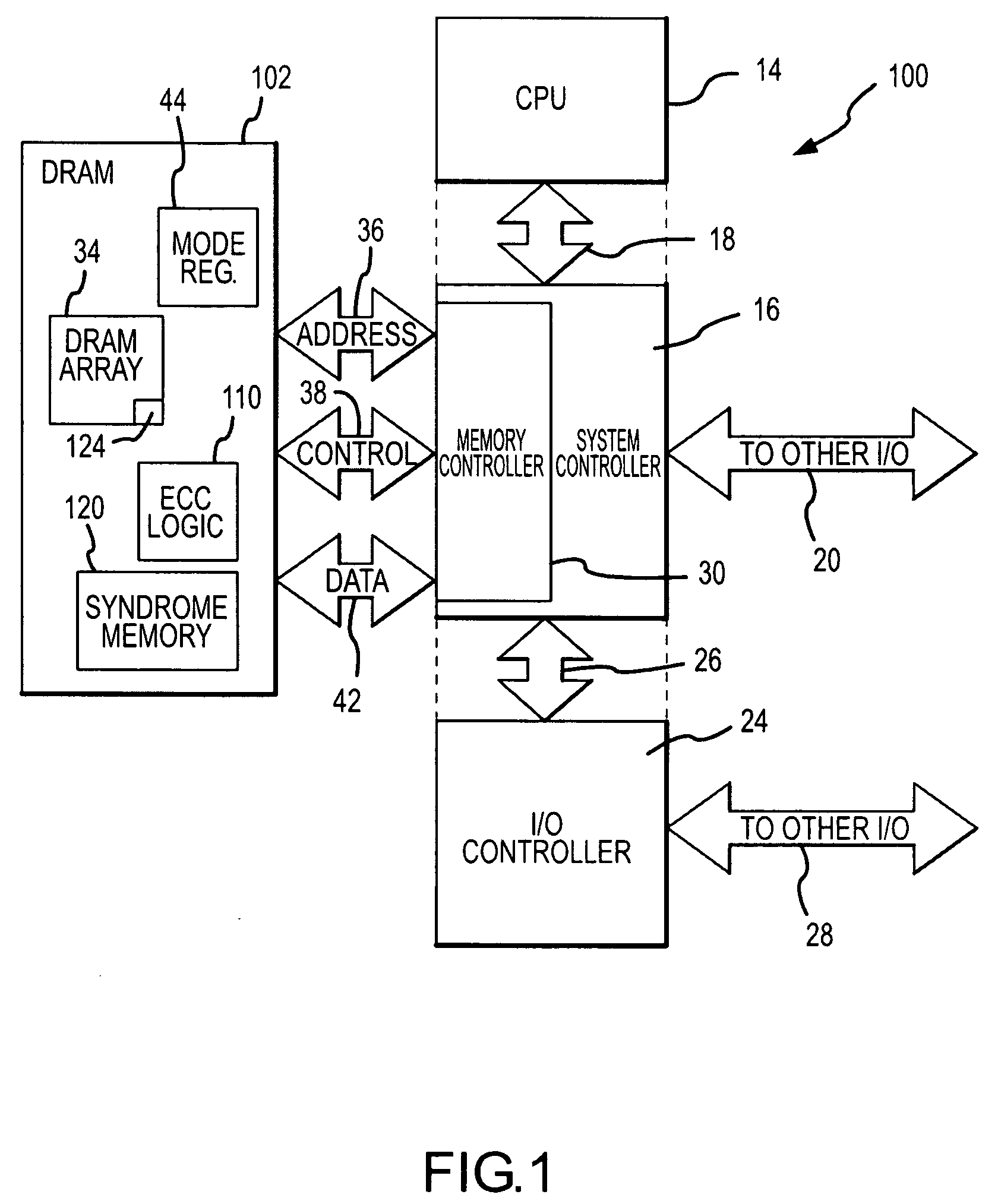
dynamic random access memory (“DRAM”) devices that consume a substantial amount of power.
In general, the power consumed by a DRAM device increases with both the capacity and the operating speed of the DRAM devices.
The power consumed by DRAM devices is also affected by their operating mode.
A DRAM device for example, will generally consume a relatively large amount of power when the memory cells of the DRAM device are being refreshed.
A relatively large amount of power is consumed when refreshing a DRAM because rows of memory cells in a memory cell array are being actuated in the rapid sequence.
As a result, DRAM refreshes tend to be particularly power-hungry operations.
Further, since refreshing memory cells must be accomplished even when the DRAM is not being used and is thus inactive, the amount of power consumed by refresh is a critical determinant of the amount of power consumed by the DRAM over an extended period.
However, reducing the refresh rate increases the risk that data stored in the DRAM memory cells will be lost.
More specifically, since, as mentioned above, DRAM memory cells are essentially capacitors, charge inherently leaks from the memory cell capacitors, which can change the value of a data bit stored in the memory cell over time.
However, current leaks from capacitors at varying rates.
Some capacitors are essentially short-circuited and are thus

Method used


Image

  • Memory system and method using partial ECC to achieve low power refresh and fast access to data
  • Memory system and method using partial ECC to achieve low power refresh and fast access to data
  • Memory system and method using partial ECC to achieve low power refresh and fast access to data

Examples


Embodiment Construction

[0017]A computer system 100 according to one embodiment of the invention is shown in FIG. 1. The computer system 100 includes a central processor unit (“CPU”) 14 coupled to a system controller 16 through a processor bus 18. The system controller 16 is coupled to input / output (“I / O”) devices (not shown) through a peripheral bus 20 and to an I / 0 controller 24 through an expansion bus 26. The I / O controller 24 is also connected to various peripheral devices (not shown) through another I / 0 bus 28.

[0018]The system controller 16 includes a memory controller 30 that is coupled to a dynamic random access memory (“DRAM”) device 102 through an address bus 36, a control bus 38, and a data bus 42. The locations in the DRAM device 102 to which data are written and data are read are designated by addresses coupled to the DRAM device 102 on the address bus 36. The operation of the DRAM device 102 is controlled by control signals coupled to the DRAM device 102 on the control bus 38.

[0019]In other e...


PUM


Abstract

A DRAM memory device includes several banks of memory cells each of which are divided into first and second sets of memory cells. The memory cells in the first set can be refreshed at a relatively slow rate to reduce the power consumed by the DRAM device. Error checking and correcting circuitry in the DRAM device corrects any data retention errors in the first set of memory cells caused by the relatively slow refresh rate. The memory cells in the second set are refreshed at a normal rate, which is fast enough that data retention errors do not occur. A mode register in the DRAM device may be programmed to select the size of the second set of memory cells.

Description

TECHNICAL FIELD[0001]This invention relates to dynamic random access memory (“DRAM”) devices, and, more particularly, to a method and system for operating a memory system in a low power mode while allowing frequently accessed data to be quickly accessed.BACKGROUND OF THE INVENTION[0002]As the use of electronic devices, such as personal computers, continues to increase, it is becoming ever more important to make such devices portable. The usefulness of portable electronic devices, such as notebook computers, is limited by the limited length of time batteries are capable of powering the device before needing to be recharged. This problem has been addressed by attempts to increase battery life and attempts to reduce the rate at which such electronic devices consume power.[0003]Various techniques have been used to reduce power consumption in electronic devices, the nature of which often depends upon the type of power consuming electronic circuits that are in the device. For example, ele...

Claims


Application Information

Patent Timeline
IPC IPC(8): G11C29/00H03M13/00
CPCG06F11/1044G11C11/406G11C11/40618G11C11/40622G11C29/52G11C2211/4062G11C2211/4067G06F11/1008G06F11/1076G11C2029/0411
Inventor PAWLOWSKI, J. THOMAS
Owner MICRON TECH INC
Why Eureka
Try Eureka