
Tone plate for keyboard-type tone plate percussion instrument, tone plate-fabricating method, tone generator unit of tone plate percussion instrument, and keyboard-type percussion instrument

a technology of keyboard-type tone plates and percussion instruments, which is applied in the direction of stringed musical instruments, instruments, musical instruments, etc., can solve the problems of increasing the difficulty of replacement, affecting the performance of the instrument, and reducing the so as to increase the degree of freedom in design and reduce the entire length and width of the tone plate

Inactive Publication Date: 2009-08-27
YAMAHA CORP
View PDF50 Cites 1 Cited by
  • Summary
  • Abstract
  • Description
  • Claims
  • Application Information

AI Technical Summary

Benefits of technology

This solution enhances design flexibility, simplifies the mounting and replacement of tone plates, and enables key transposition, providing a more versatile and efficient keyboard-type percussion instrument.

Problems solved by technology

In the keyboard-type tone plate percussion instrument based on the first prior art, however, the tone plate group and the resonance box are fixed to the musical instrument main body independently of each other, making it difficult to carry out the mounting operation thereof to the musical instrument.
In addition, the tone plates must be mounted one by one, thus further complicating the tone plate mounting operation.
Upon such replacement, a fine adjustment is required of the distance and positional relation between the tone plate group and the resonance box in order to maintain the desired sounding capability of the tone plate percussion instrument, which further increases the difficulty of replacement.
It is therefore impossible to carry out key transposition, for example.
The necessity for satisfying the above requirement for the tone plate size poses a problem that the degree of freedom in design decreases.
For example, this results in increase in the entire instrument size, especially in a case where the keyboard-type tone plate percussion instrument includes a large number of tone plates so as to cover a wide range of pitch.

Method used


Image

  • Tone plate for keyboard-type tone plate percussion instrument, tone plate-fabricating method, tone generator unit of tone plate percussion instrument, and keyboard-type percussion instrument
  • Tone plate for keyboard-type tone plate percussion instrument, tone plate-fabricating method, tone generator unit of tone plate percussion instrument, and keyboard-type percussion instrument
  • Tone plate for keyboard-type tone plate percussion instrument, tone plate-fabricating method, tone generator unit of tone plate percussion instrument, and keyboard-type percussion instrument

Examples


first embodiment

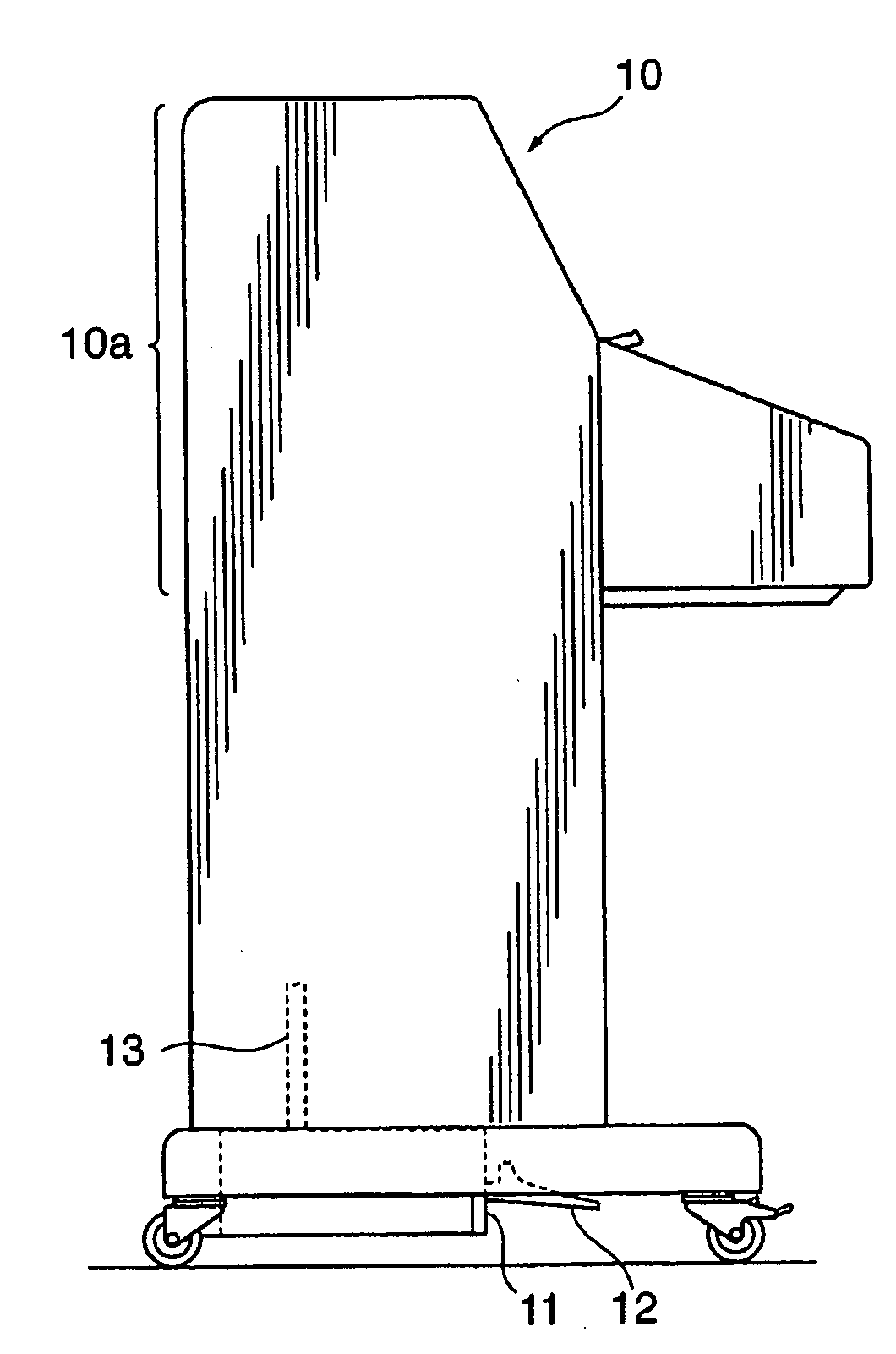
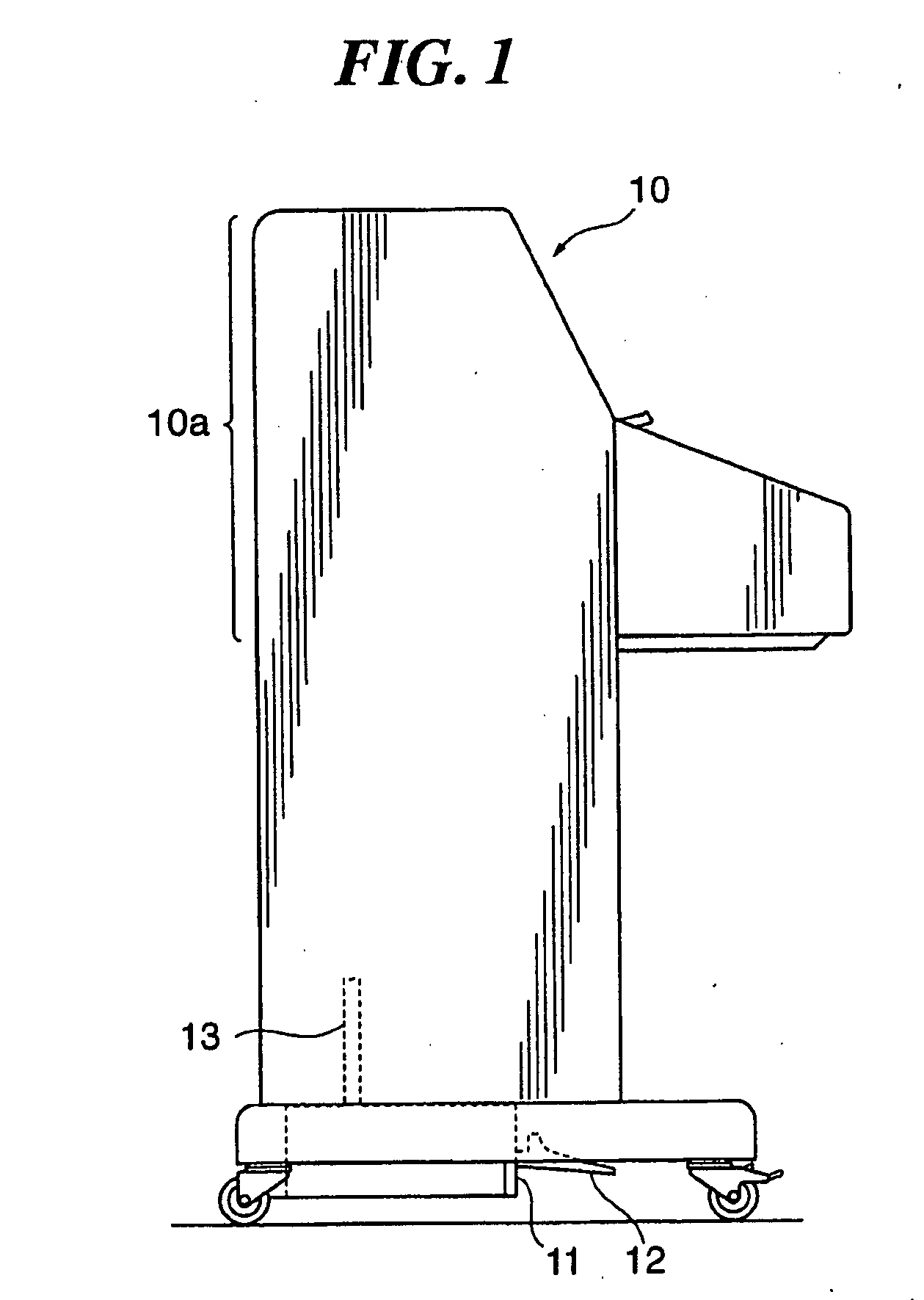
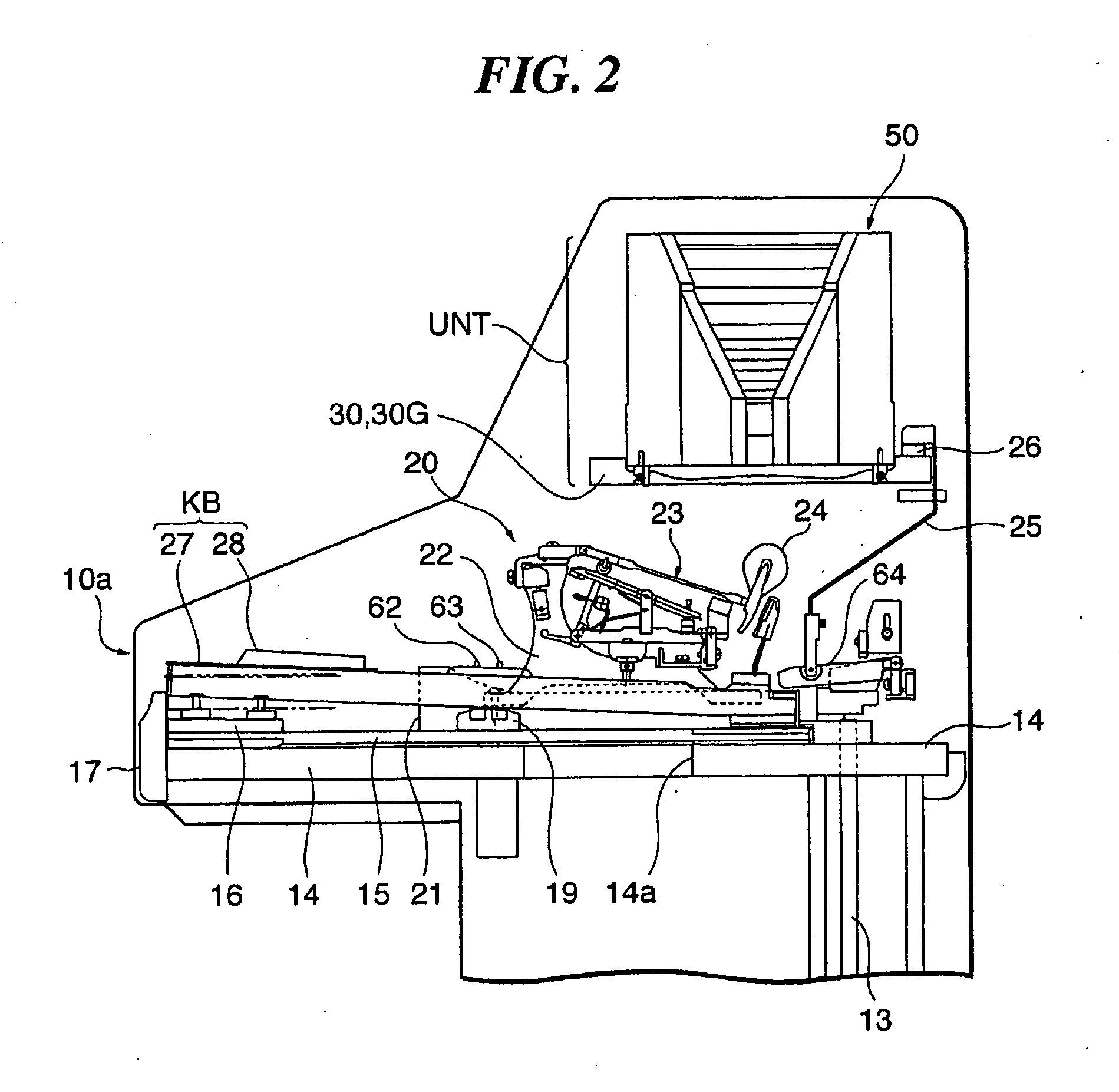
[0075]FIG. 1 is a left side view of a keyboard instrument that is constructed as a keyboard-type tone plate percussion instrument to which is applied a tone generator unit that includes a plurality of tone plates, which are sounding members according to the present invention. Roughly speaking, the keyboard instrument 10 is analogous in appearance to an upright piano, but does not include any strings. Instead, the keyboard instrument 10 includes tone plates that are similar to those of a celesta and provided in an upper half 10a of the keyboard instrument 10. When struck, each of the tone plates vibrates and generates a musical tone. The keyboard instrument 10 includes a resonance box that causes the musical tone generated by the corresponding tone plate to resonate therein. As mechanisms for striking the tone plates, there are provided mechanisms similar to action mechanisms for a grand piano but not for an upright piano.

[0076]In the following, the side of the keyboard instrument 10...

fourth embodiment

[0138]FIG. 14A is a front view showing a mechanism for key transposition in a keyboard instrument constructed as a keyboard-type tone plate percussion instrument to which is applied a tone generator unit that includes a plurality of tone plates, which are sounding members according to the In FIG. 14A, the left side of the keyboard instrument is shown. FIG. 14B is an inner side view showing a left side plate of the keyboard instrument.

third embodiment

[0139]In the mechanism for key transposition, the coupling rod 82, pivot shaft 83, L-shaped link 84, pivot shaft 86, and support 115 have the same construction as those of the third embodiment except for their shapes and lengths. As shown in FIGS. 14A and 14B, on an inner side surface (right side surface) of the side plate 18L, there is provided a hand-operated lever 87 for pivotal motion around a pivot shaft 90. The lever 87 has its intermediate portion that is coupled to a lower end of the coupling rod 82 so as to be pivotable around a pivot shaft 89.

[0140]Further, a stepped positioning stopper portion 88 is formed in the inner side surface (right side surface) of the side plate 18. The stopper portion 88 is formed into a circular shape, as seen in side view, extending in the direction in which the lever 87 is pivoted (refer to FIG. 14B), and is comprised of a plurality of steps 88a. The distance between vertically adjacent ones of the steps 88a corresponds to a distance required ...


PUM


Abstract

A tone plate which makes it easy to reduce the entire length and width thereof, thus increasing the degree of freedom in design. The tone plate includes an antinode portion, front and rear ends, and first and second supporting holes which are located closer to the front and rear ends than to the antinode portion and at which a vibration node can be formed. There are provided first and second mass concentrating portions extending toward the front and rear ends from locations on a side close to the first and rear ends with respect to the supporting holes. First and second thinner portions are respectively provided between the antinode portion and the supporting holes. The tone plate vibrates to generate a musical tone of a specific tone pitch when struck with being supported at the supporting holes.

Description

CROSS-REFERENCE TO RELATED APPLICATIONS[0001]This application is a divisional of U.S. patent application Ser. No. 11 / 610,018, filed Dec. 13, 2006, the entirety of which is incorporated herein by reference.BACKGROUND OF THE INVENTION[0002]1. Field of the Invention[0003]The present invention relates to a tone plate for use in a keyboard-type tone plate percussion instrument, which is adapted to vibrate to thereby generate a musical tone of a specific tone pitch when struck, a method for fabricating the tone plate, a tone generator unit of a tone plate percussion instrument including tone plates and a resonance box for causing musical tones generated by the tone plates to resonate therein, and a keyboard-type percussion instrument.[0004]This application claims priority to Japanese Patent Application Nos. 2005-359315, 2005-359317, and 2005-359318, the contents of which are incorporated herein by reference.[0005]2. Description of the Related Art[0006]As disclosed in Japanese Utility Mode...

Claims


Application Information

Patent Timeline
Patent Type & Authority Applications(United States)
IPC IPC(8): G10D13/08
CPCG10D13/085G10D13/09G10C3/16G10C5/00G10D13/08
Inventor TERADA, NORISHIGE
Owner YAMAHA CORP
Learn More