Cleaning device

a cleaning device and cleaning technology, applied in the field of cleaning devices, can solve the problems of increasing the difficulty of sanitizing frequently-used areas in hospitals and institutions, and increasing the difficulty of providing a germ-free environment, so as to achieve the effect of minimizing the contact with contaminan

Inactive Publication Date: 2009-08-27
HO EDWARD
View PDF33 Cites 16 Cited by
  • Summary
  • Abstract
  • Description
  • Claims
  • Application Information

AI Technical Summary

Benefits of technology

[0011]It is therefore an object of the present invention to provide a hands-free, automated cleaning and disinfecting device for an enclosure with at least one drain

Problems solved by technology

Oftentimes, people in hospitals and institutions contract additional infections because of the hospital or institution's inability to maintain a sterile and sanitary environment.
It is getting harder and increasingly more challenging to provide a germ-free environment, especially for those who have weakened immune systems.
Sanitizing frequently-used areas in hospital and institutions is in itself a dirty and time-consuming job, and even with the best cleaning staff available, if it still difficult to maintain a sterile environment.
In addition to soiling from the incomplete removal of waste, microorganisms, bacteria, mineral deposits commonly found in water, paper products, and any other unsanitary items, the presence of a default amount of water at the end of each disposal cycle can lead to deposits that are difficult to remove during a disposal cycle.
Such requirements usually make the task of cleaning a toilet unappealing.
The manual scrubbing associated with typical toilet bowl cleaning methods has some degree of effectiveness, and is arguably efficient, but, by itself, scrubbing is most likely ineffective in disinfec

Method used


Image

  • Cleaning device
  • Cleaning device
  • Cleaning device

Examples


Embodiment Construction

[0030]Reference will now be made in detail to various embodiments of the invention, one or more examples of which are illustrated in the accompanying drawings. Each example is provided by way of explanation of the invention, and by no way limiting the present invention. In fact, it will be apparent to those skilled in the art that various modifications, combination, additions, deletions and variations can be made in the present invention without departing from the scope or spirit of the present invention. For instance, features illustrated or described as part of one embodiment can be used in another embodiment to yield a still further embodiment. It is intended that the present invention covers such modifications, combinations, additions, deletions, applications and variations come within the scope of the appended claims and their equivalents.

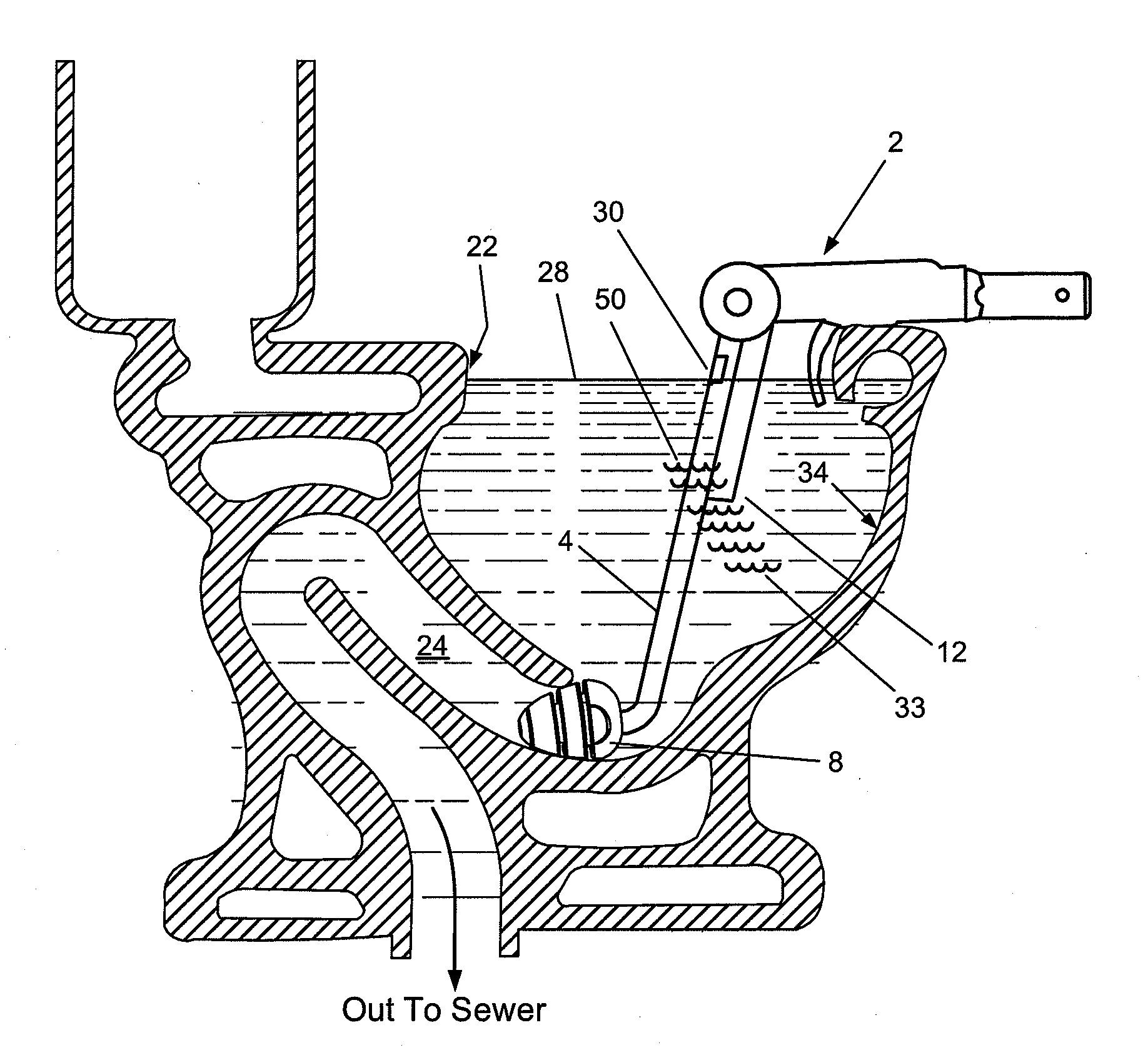
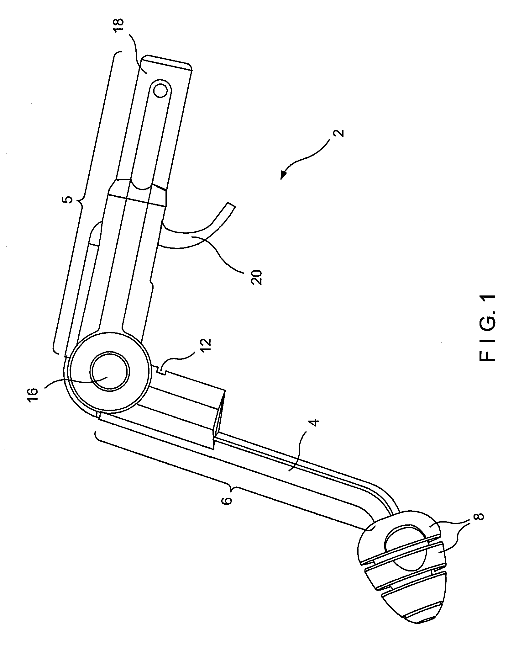
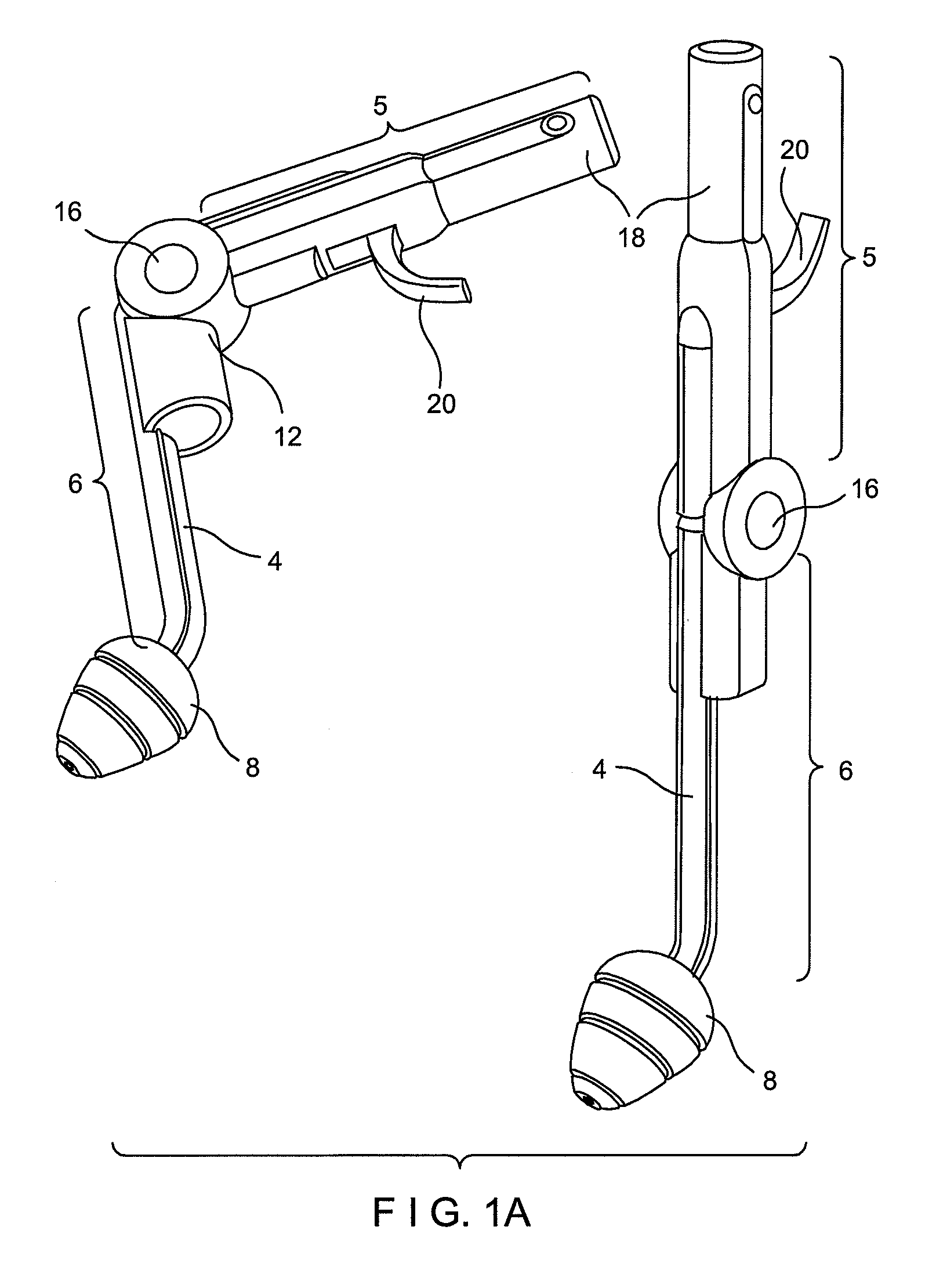
[0031]The instant invention is directed to a hands-free cleaning device for cleaning an inside surface of any enclosure having at least one d...


PUM

PropertyMeasurementUnit
Frequencyaaaaaaaaaa
Frequencyaaaaaaaaaa
Frequencyaaaaaaaaaa

Abstract

A cleaning device for cleaning any enclosure having at least one drainage capable of enclosing one liquid. The enclosure including but, not limited to a toilet bowl, a bidet, a bathtub, a sink, a reservoir, a tank and, a shower stall. The cleaning device comprising an elongated member having a sidewall, an outer surface, an inner surface, a first end, a second end, and a substantially hollow cavity. The first end and the second end of the elongated member can either be integral or be connected by a connecting means. The cleaning device also includes a stopper disposed on the first end and a gripping member removably attached to the second end of the elongated member. A liquid level regulator is provided on the cleaning device in order to control and regulate the amount of liquid disposed in an enclosure to be cleaned in order to maximize cleaning without causing overflowing. Cleaning is accomplished by a controlling means-controlling at least one agitating means operating at an optimal frequency. The cleaning device also has a safety circuit to ensure the cleaning device is positioned at an optimal angle with sufficient liquid present in the enclosure to be cleaned.

Description

INCORPORATION BY REFERENCE[0001]All documents cited or referenced herein (“herein cited documents”), and all documents cited or referenced in herein cited documents, together with any manufacturer's instructions, descriptions, product specifications, and product sheets for any products mentioned herein or in any document incorporated by reference herein, are hereby incorporated herein by reference, and may be employed in the practice of the invention.FIELD OF THE INVENTION[0002]The present invention directs to a cleaning device for a toilet bowl, a bidet, a sink, a bathtub, a reservoir and / or any enclosure with drainage. More particularly, the present invention teaches and claims a cleaning device and method for cleaning an enclosure having at least one drainage, for example, a toilet bowl, in which the device seals the water outlet of the bowl and agitates the trapped water to clean the interior surfaces of the toilet bowl.BACKGROUND OF THE INVENTION[0003]Personal hygiene has alway...

Claims


Application Information

Patent Timeline
IPC IPC(8): B08B3/12B08B1/00
CPCB08B3/12E03D9/00E03C1/308B08B9/093
Inventor HO, EDWARD
Owner HO EDWARD
Why Eureka
Try Eureka