
Flat Heavy-Duty Pneumatic Radial Tire and Method of Manufacturing the Same

a pneumatic radial tire and heavy-duty technology, applied in the field of flat heavy-duty pneumatic radial tire, can solve the problems of tire wear, tire durability and partial wear resistance deterioration, and tire wear partial wear, so as to improve durability and drive stability.

Inactive Publication Date: 2009-08-27
THE YOKOHAMA RUBBER CO LTD
View PDF2 Cites 26 Cited by
  • Summary
  • Abstract
  • Description
  • Claims
  • Application Information

AI Technical Summary

Benefits of technology

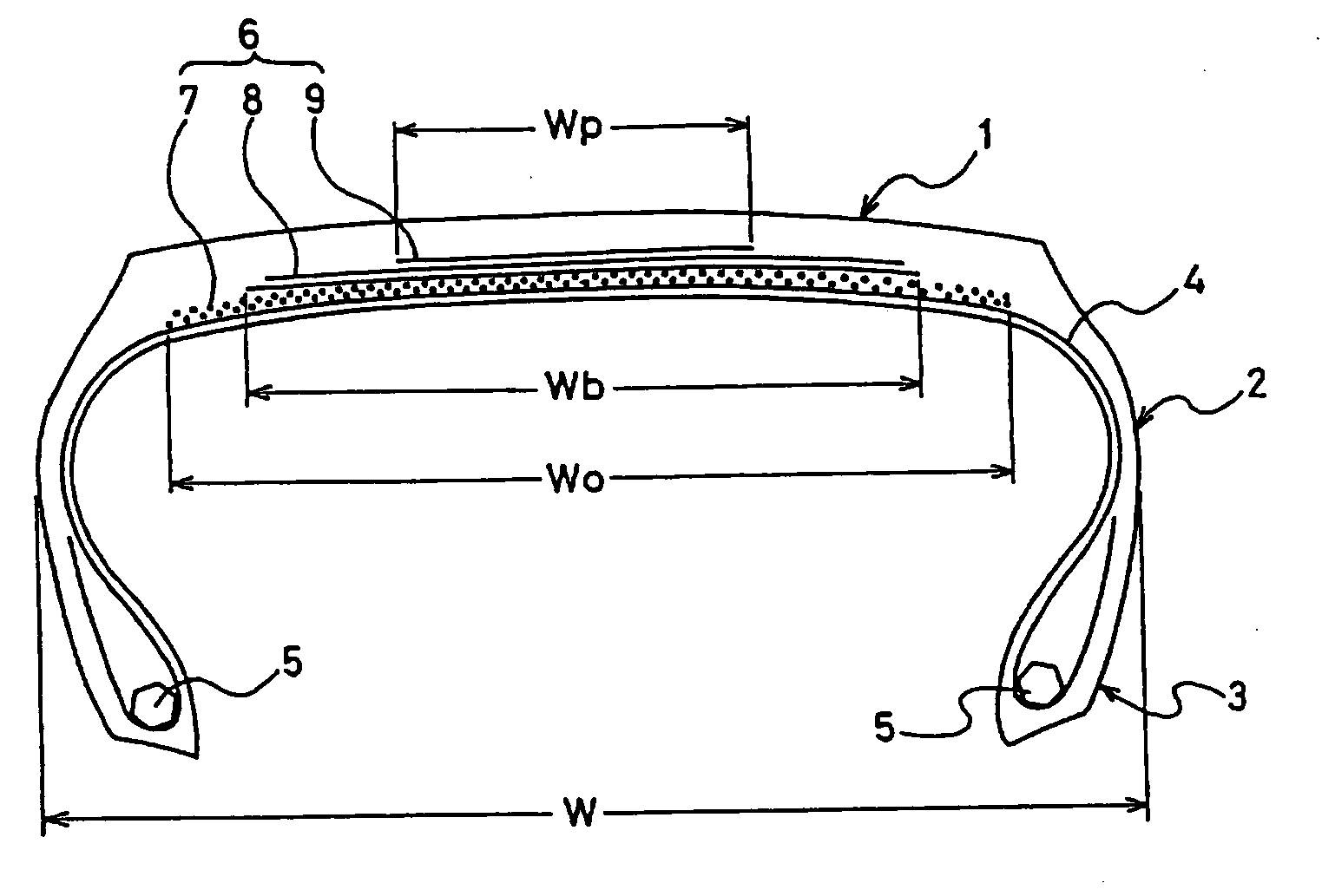
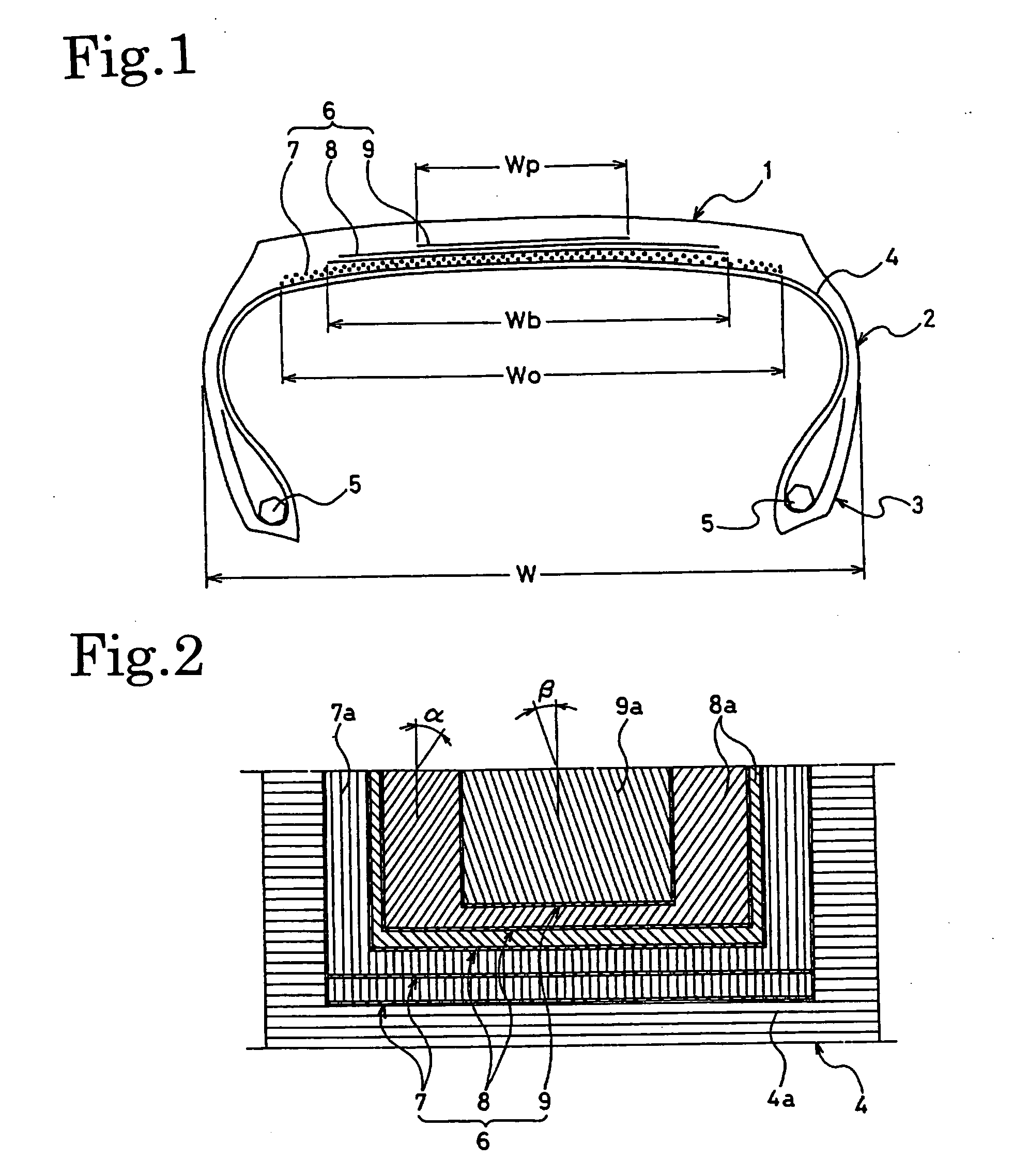
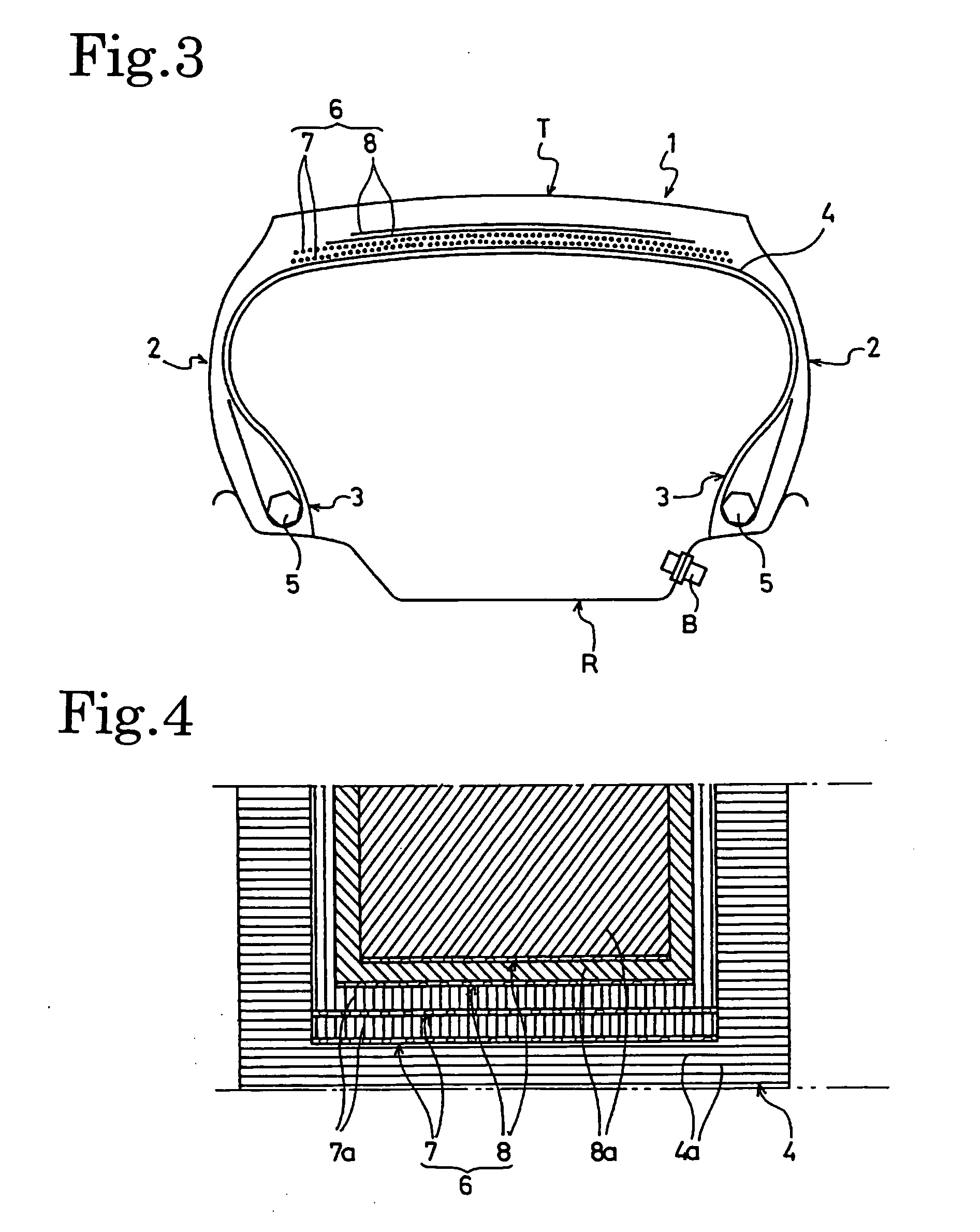
The present invention provides a flat heavy-duty pneumatic radial tire with improved durability, partial-wear resistance, and driving stability. This is achieved by using a special steel cord belt layer made of a 0-degree belt layer and two layers of bias belt layers. The 0-degree belt layer is made of steel cords with a non-linear stress-strain relationship and is arranged at an angle of substantially 0° to the outer periphery of the tire. The bias belt layers are arranged at an angle of 15° to 35° to the 0-degree belt layer. The tire also includes a protection belt layer made of steel cords arranged at an angle of 15-30 degrees to the outer periphery of the tire. The method of manufacturing the tire involves curing the uncured tire in a mold, assembling it with a rim, and cooling it down to normal temperature while inflating it. The post-inflation process stretches out the steel cords in the 0-degree belt layer, which makes the tire more durable and stable.

Problems solved by technology

A problem to be solved for the purpose of causing such ultra-flat radial tires to produce their full running performances is how to make their wide treads evenly contact road surfaces.
That is because, if the treads unevenly contact the road surfaces, this brings about a problem that the durabilities and partial-wear resistances of the tires are deteriorated.
In addition, because the interlayer shearing stress increases in the edge portions of the belt layers in the flat radial tire, a delamination failure occurs at the edges, and accordingly leads to decrease in the durability of the tire, causing partial-wear of the tire.
However, the effect concerning the acquired durability and partial-wear resistance does not necessarily reach a satisfactory level, and a further improvement is awaited.
In the case of this type of steel cords having the non-linear stress-strain relationship, however, it is likely that some extensible parts in the steel cords are not fully extended when stretched, and remain yet not to be extended, even after the steel cords are made in cure.
For this reason, when a cured tire is filled with an internal pressure, the external shape of the tire grows larger than its design dimensions, and this overgrowth leads to decrease in the durability of the tire and deterioration of the driving stability of the tire.

Method used


Image

  • Flat Heavy-Duty Pneumatic Radial Tire and Method of Manufacturing the Same
  • Flat Heavy-Duty Pneumatic Radial Tire and Method of Manufacturing the Same
  • Flat Heavy-Duty Pneumatic Radial Tire and Method of Manufacturing the Same

Examples


example 1

[0050]

First Layer (0-degree Belt Layer)Belt Width:75% of the tire total width WCord Angle:0°Cord Structure:3 × (1 + 5) × 0.25 mm, 25 ends / 50 mmSecond Layer (0-degree Belt Layer)Belt Width:75% of the tire total width WCord Angle:0° C.Cord Structure:3 × (1 + 5) × 0.25 mm, 25 ends / 50 mmThird Layer (Bias Belt Layer)Belt Width:53% of the tire total width WCord Angle:50° (inclined left)Cord Structure:3 + 9 × 0.22 mm, 21 ends / 50 mmFourth Layer (Bias Belt Layer)Belt Width:48% of the tire total width WCord Angle:50° (inclined right)Cord Structure:3 + 9 × 0.22 mm, 21 ends / 50 mm

example 2

[0051]

First Layer (0-degree Belt Layer)Belt Width:75% of the tire total width WCord Angle:0° C.Cord Structure:3 × (1 + 5) × 0.25 mm, 25 ends / 50 mmSecond Layer (0-degree Belt Layer)Belt Width:75% of the tire total width WCord Angle:0°Cord Structure:3 × (1 + 5) × 0.25 mm, 25 ends / 50 mmThird Layer (Bias Belt Layer)Belt Width:53% of the tire total width WCord Angle:50° (inclined left)Cord Structure:3 × + 9 × 0.22 mm, 21 ends / 50 mmFourth Layer (Bias Belt Layer)Belt Width:48% of the tire total width WCord Angle:50° (inclined right)Cord Structure:3 + 9 × 0.22 mm, 21 ends / 50 mmFifth Layer (Bias Belt Layer)Belt Width:29% of the tire total width WCord Angle:20° (inclined right)Cord Structure:3 × 0.20 mm + 6 × 0.35 mm, 15 ends / 50 mm

example 3

[0052]

First Layer (0-degree Belt Layer)Belt Width:75% of the tire total width WCord Angle:0°Cord Structure:3 × (1 + 5) × 0.25 mm, 25 ends / 50 mmSecond Layer (0-degree Belt Layer)Belt Width:two belt layers each with a beltwidth of 25% of the tire totalwidth W being arrangedhorizontally with an interval of27% of the tire total width Win betweenCord Angle:0°Cord Structure:3 × (1 + 5) × 0.25 mm, 25 ends / 50 mmThird Layer (Bias Belt Layer)Belt Width:53% of the tire total width WCord Angle:50° (inclined left)Cord Structure:3 + 9 × 0.22 mm, 21 ends / 50 mmFourth Layer (Bias Belt Layer)Belt Width:48% of the tire total width WCord Angle:50° (inclined right)Cord Structure:3 + 9 × 0.22 mm, 21 ends / 50 mm


PUM

PropertyMeasurementUnit
equilibrium angleaaaaaaaaaa
angleaaaaaaaaaa
equilibrium angleaaaaaaaaaa

Abstract

A flat heavy-duty pneumatic radial tire having a 0-degree belt layer formed of steel cords and increased in durability, wherein multiple plies of steel cord belt layers (6) are disposed on the outer periphery of a carcass layer (4). The steel cord belt layers (6) includes at least one ply of the 0-degree belt layer with a cord angle of substantially 0° relative to the circumferential direction of the tire and at least two plies of bias belt layers (8) with a cord angle substantially equal to an equilibrium angle of within a range of 45° to 65° relative to the circumferential direction of the tire. The tire is manufactured as follows. The tire cured and molded in a mold is released from the mold, assembled with a rim to be inflated while the tire is hot, and then cooled to normal temperature under the inflated condition.

Description

TECHNICAL FIELD[0001]The present invention relates to a flat heavy-duty pneumatic radial tire and a method of manufacturing the same. More specifically, the present invention relates to a flat heavy-duty pneumatic radial tire with further improved durability and partial-wear resistance as well as an enhanced driving stability, and to a method of manufacturing the same.BACKGROUND ART[0002]In recent years, not only pneumatic radial tires for passenger cars but also pneumatic radial tires for heavy duty are constructed flat with an increasingly lower profile, and the number of ultra-flat tires with an aspect ratio of 60% or less is on rise. In the Japanese market, ultra-flat pneumatic radial tires for heavy duty started particularly with low-floor buses, and are now widely used. A problem to be solved for the purpose of causing such ultra-flat radial tires to produce their full running performances is how to make their wide treads evenly contact road surfaces. That is because, if the t...

Claims


Application Information

Patent Timeline
Patent Type & Authority Applications(United States)
IPC IPC(8): B60C9/18B29C35/02
CPCB60C9/22B60C9/20
Inventor KABE, KAZUYUKIITOH, TAKEHIKOISOBE, TETSUOGAWA, YUKIHIRO
Owner THE YOKOHAMA RUBBER CO LTD
Learn More