Probe device having a clip-on wireless system for extending probe tip functionality

Inactive Publication Date: 2009-08-27
AGILENT TECH INC
View PDF6 Cites 145 Cited by
  • Summary
  • Abstract
  • Description
  • Claims
  • Application Information

AI Technical Summary

Benefits of technology

[0006]In accordance with the invention, a probe device for use in measuring electrical signals on a DUT is provided that comprises a probe device housing, circuitry disposed within the housing, and a clip-on wirele

Problems solved by technology

It would be desirable to be able to add various types of functionality to the probe device near the probe tips, but doing so is difficult for a variety of reasons.
Consequently, any features that require digital signals and/or power supplies generally cannot be added to the probe de

Method used


Image

  • Probe device having a clip-on wireless system for extending probe tip functionality
  • Probe device having a clip-on wireless system for extending probe tip functionality
  • Probe device having a clip-on wireless system for extending probe tip functionality

Examples


Embodiment Construction

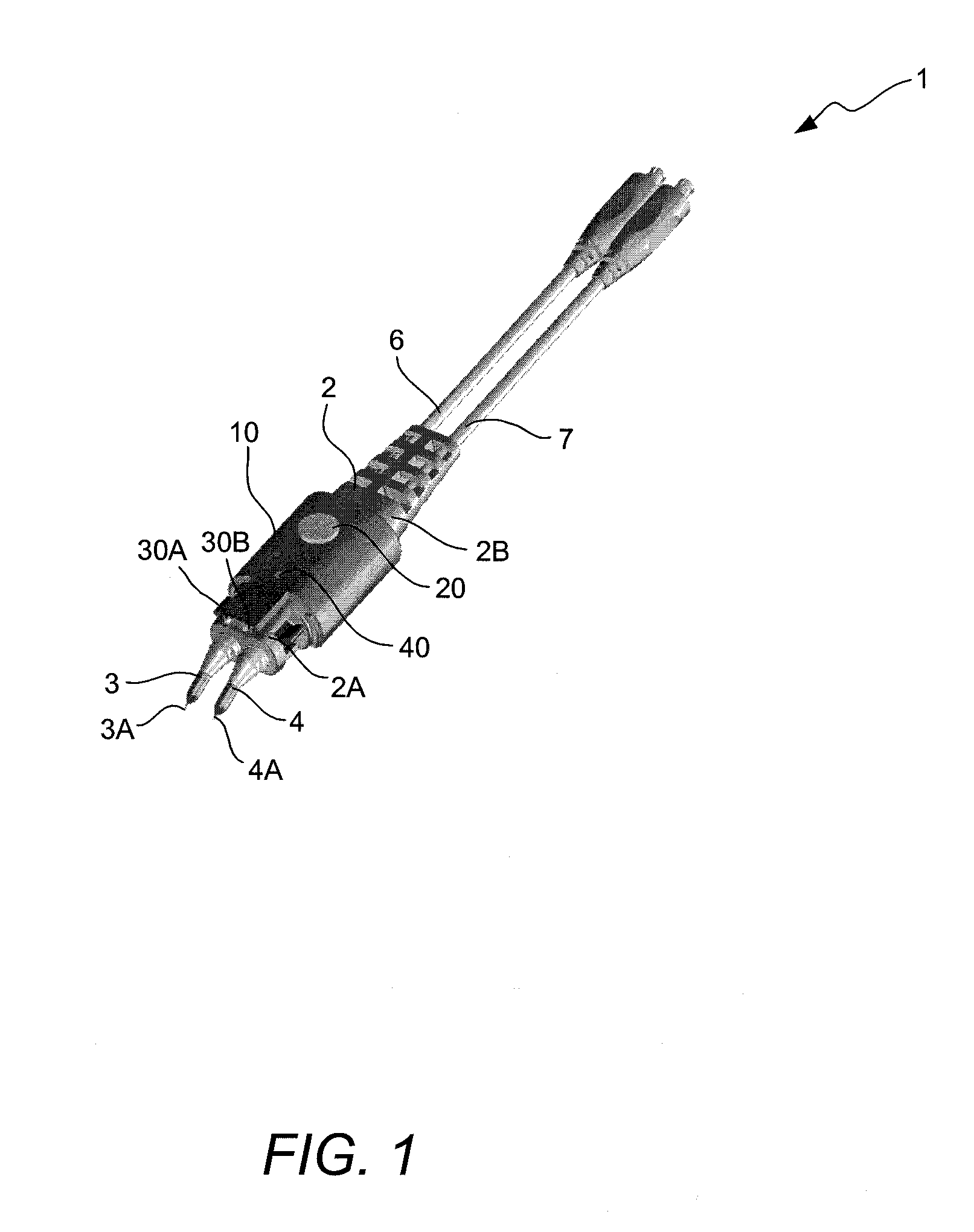
[0019]In accordance with the invention, a probe device is provided that has a clip-on wireless device attached thereto for communicating over a wireless communication link with a wireless transceiver connected to test equipment. In accordance with an embodiment, the clip-on wireless device includes one or more components that provide additional functionality to the probe device over that which is currently available on probe devices. Such components may include, for example, run / stop buttons, activity indicators, “headlight” LEDs, a power saving mode circuit, etc.

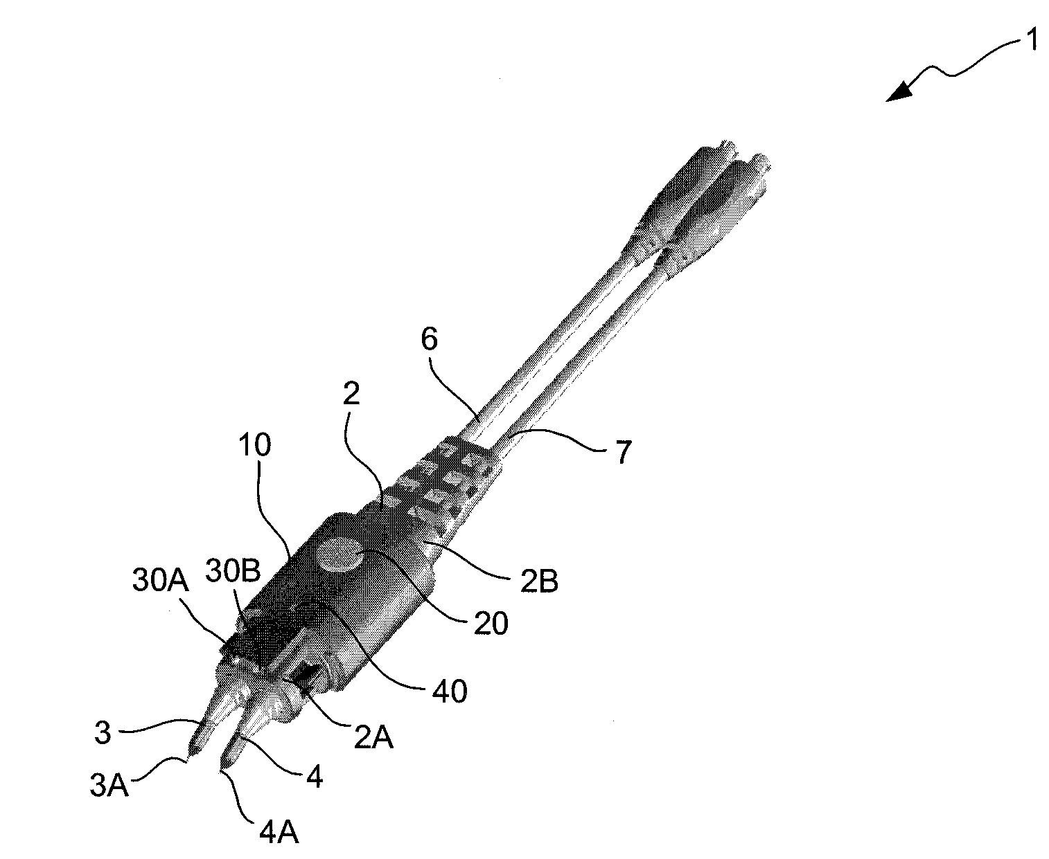
[0020]FIG. 1 illustrates a top perspective view of an electrical probe device 1 equipped with a clip-on wireless device 10 in accordance with an illustrative embodiment of the invention. It should be noted that the invention is not limited with respect to the type or configuration of the probe device with which the clip-on wireless device of the invention is used. For illustrative purposes, the probe device with which the c...


PUM


Abstract

A probe device is provided that has a clip-on wireless device attached thereto for communicating over a wireless communication link with test equipment having a wireless transceiver attached thereto. The clip-on wireless device may have one or more components that provide additional functionality to the probe device over that which is currently available on most probe devices. Such components may include, for example, run/stop buttons, activity indicators, “headlight” LEDs, etc

Description

TECHNICAL FIELD OF THE INVENTION[0001]The invention relates to electrical probe devices used to measure electrical signals on conductors of a device under test (DUT). More particularly, the invention relates to a clip-on wireless system that is attachable to a probe device.BACKGROUND OF THE INVENTION[0002]A variety of probe devices are used to electrically probe a DUT. For example, a differential probe device is a device having two arms, sometimes referred to as “substrates” or “blades”, each of which has an electrically conductive tip secured to the distal end thereof. During testing of a DUT, the tips are placed in contact with respective conductors of the DUT for sensing electrical signals propagating through the conductors of the DUT. The electrical signals sensed by the tips are passed from the tips to other electrical circuits disposed within the probe device housing that condition the sensed electrical signals. The arms are each electrically coupled at their proximal ends to ...

Claims


Application Information

Patent Timeline
IPC IPC(8): H04B10/22
CPCG01R1/06788G01R31/3025G01R1/07
Inventor SWAIM, JASON A.JOHNSON, KENNY
Owner AGILENT TECH INC
Why Eureka
Try Eureka