
Method of Monitoring a Surface Feature and Apparatus Therefor

a surface feature and monitoring method technology, applied in the field of monitoring a surface feature and an apparatus, can solve the problems of inaccurate measurements, labor-intensive manual techniques, and require examination and contact by skilled personnel, and achieve the effects of low processing requirements, simple, and inexpensiv

Active Publication Date: 2009-08-27
ARANZ HEALTHCARE
View PDF31 Cites 65 Cited by
  • Summary
  • Abstract
  • Description
  • Claims
  • Application Information

AI Technical Summary

Benefits of technology

[0098]There are thus provided methods of measuring wounds that are simple, inexpensive, repeatable and may be performed remotely. The methods utilise human image processing capabilities to minimise the processing requirements.
[0099]The methods do not require the placement of articles near the wound and allow historical comparison of a wound. The apparatus are portable with relatively low processing requirements and enable records to be sent wirelessly for evaluation and storage.

Problems solved by technology

Manual techniques are typically labour-intensive and require examination and contact by skilled personnel.
Such measurements may be inaccurate and there may be significant variation between measurements made by different personnel.
Further, these approaches may not preserve any visual record for review by an expert or for subsequent comparison.
It is often undesirable to place a reference object near to a wound and this requires an additional cumbersome step for a user and risks contamination of the wound.
Further, when the target is not in the plane of the wound, or if the wound is not planar, there will be errors in any area calculation.
Systems utilising stereoscopic vision and automated boundary determination are known but they are expensive, complex, bulky and require significant computational power.
Further, automated identfication of the boundary of a wound may be inaccurate and variable.
While this consistently positions the camera a desired distance from the surface to be photographed and therefore sets the scale of the image, it is unwieldy and requires undesirable contact with the skin, risking contamination of the wound.
However, use of this image data is limited and the computing device is effectively used simply to allow notes to be taken.

Method used


Image

  • Method of Monitoring a Surface Feature and Apparatus Therefor
  • Method of Monitoring a Surface Feature and Apparatus Therefor
  • Method of Monitoring a Surface Feature and Apparatus Therefor

Examples


first embodiment

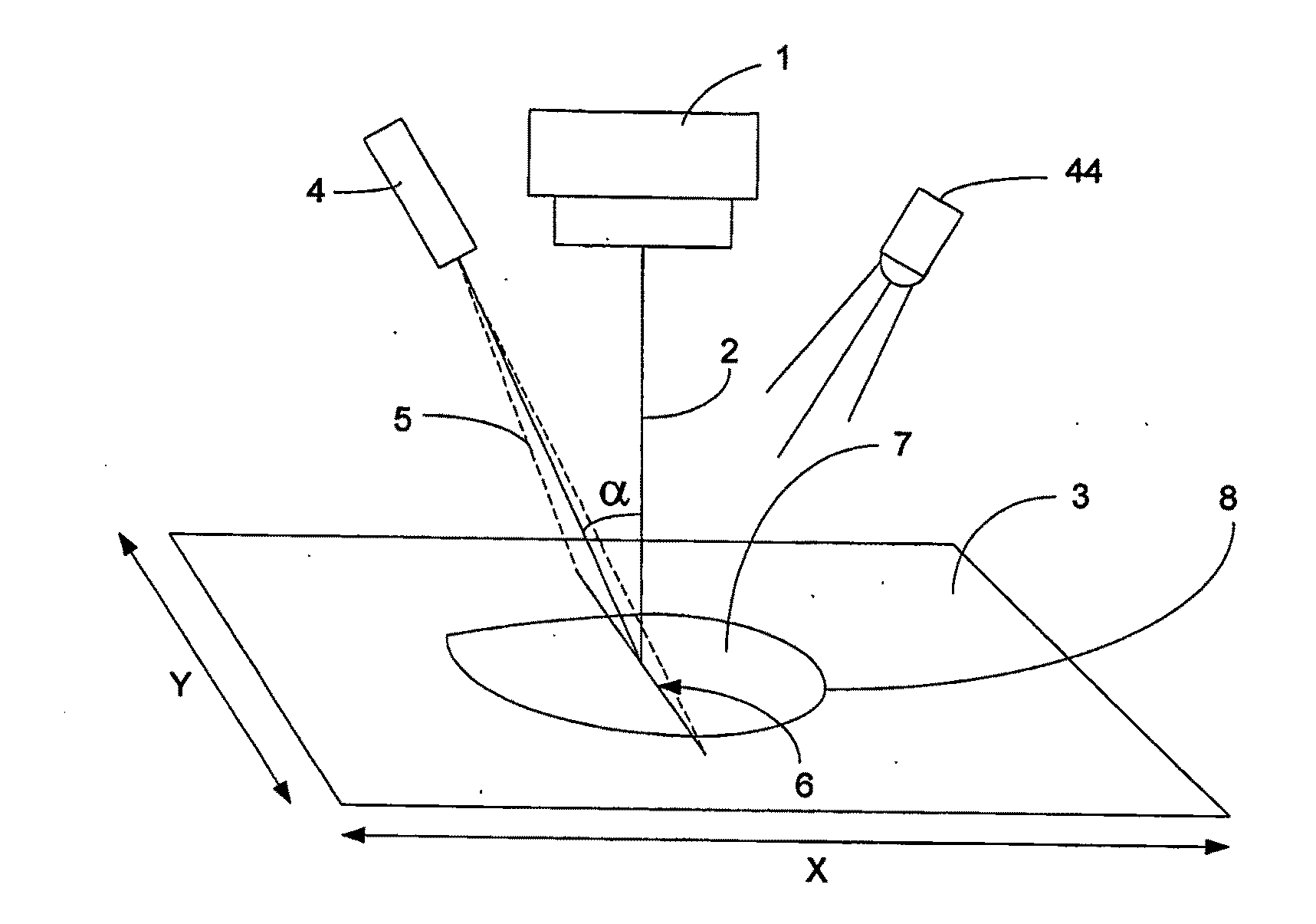
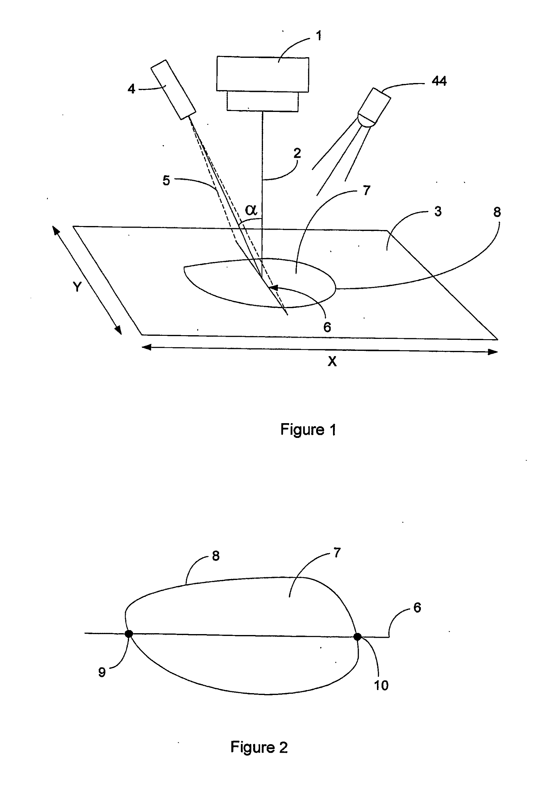
[0059]Referring to FIG. 1 the general principle of operation of the invention will be described. A camera 1 has an optical axis 2 and an image capture region 3. Laser 4 is disposed in a fixed angular relationship to optical axis 2 so that the fan beam 5 is disposed at angle a to optical axis 2. In this embodiment laser 4 generates a single stripe 6. Alternatively a laser projecting a single dot could be used. The camera 1 is preferably a high resolution digital colour camera. Optionally, an illumination means (such as a white LED 44 for low power applications) can be used to give relatively constant background lighting.

[0060]In use the assembly of camera 1 and laser 4 is directed so that optical axis 2 is aligned with the central region of wound 7. Laser 4 projects stripe 6 across wound 7 and the image is captured by camera 1. It will be appreciated that due to the fixed angular relationship of the laser fan beam 5 and the optical axis 2 that the distance of points of stripe 6 from ...

second embodiment

[0063]In a second embodiment an image may be captured in the same fashion except that the stripe need not be aligned with the optical axis of the camera. An image as shown in FIG. 2 may be obtained. Points 9 and 10, where the outline 8 of wound 7 intersects stripe 6, may be used to calculate scale. From the locations of points 9 and 10 in the image 3 their corresponding (x, y, z) coordinates can be obtained using the known relationship of the laser-camera system. Thus a scale factor may be determined based on the x,y,z coordinates of points 9 and 10 to scale the area 7 to produce a scaled value. Whilst this technique does not require a user to align the stripe with the optical axis it still suffers from the limitations of the technique described above.

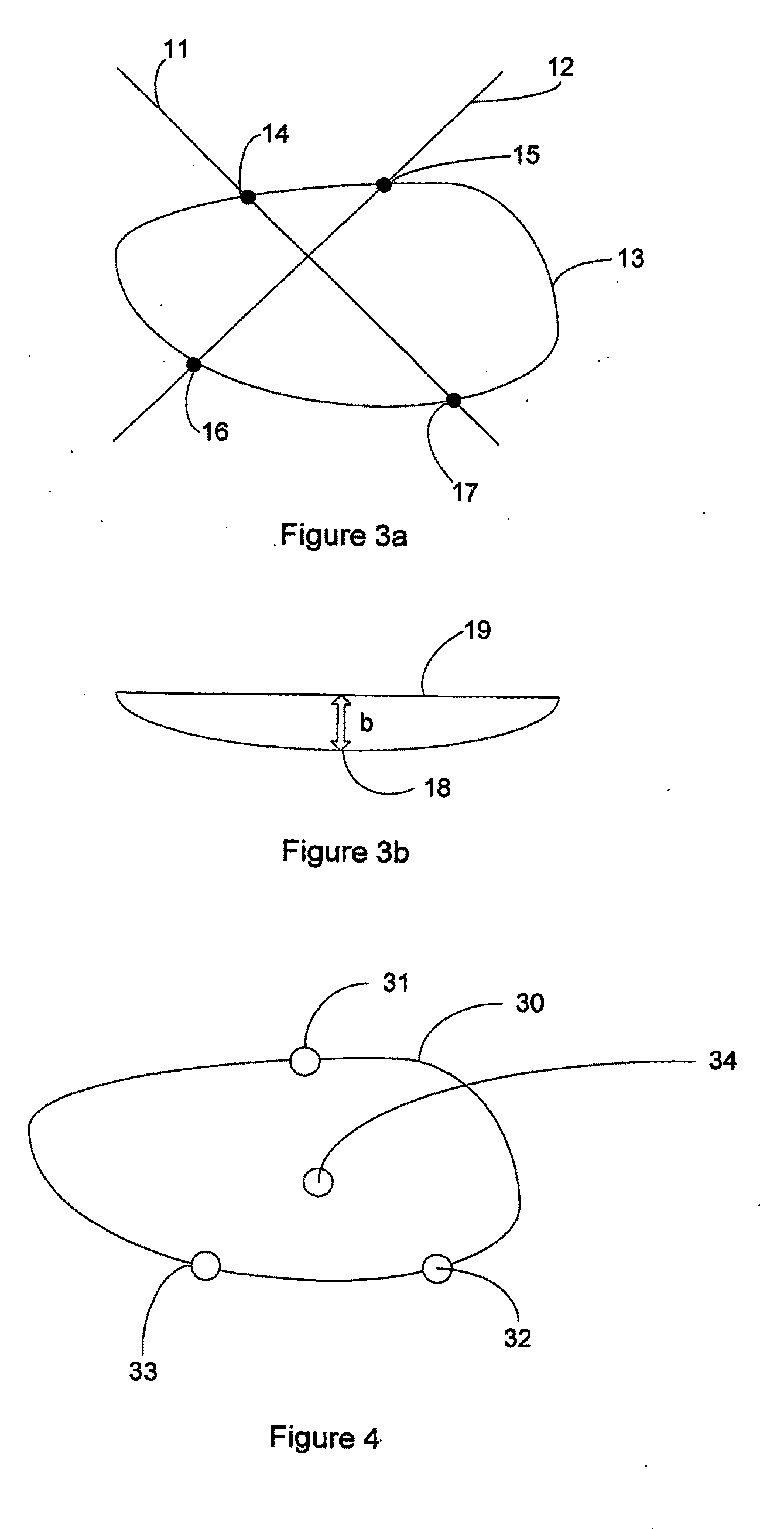
[0064]In one embodiment laser 4 projects structured light in the form of laser cross hairs onto the image capture area. An image captured according to this embodiment is shown in FIG. 3a. The laser stripes 11 and 12 captured in the ima...


PUM


Abstract

Dimensions of a surface feature are determined by capturing an image of the surface feature and determining a scale associated with the image. Structured light may be projected onto the surface, such that the position of structured light in the captured image allows determination of scale. A non-planar surface may be unwrapped. The surface may alternatively be projected into a plane to correct for the scene being tilted with respect to the camera axis. A border of the surface feature may be input manually by a user. An apparatus and system for implementing the method are also disclosed.

Description

FIELD OF THE INVENTION[0001]The invention relates to a method of monitoring a surface feature and an apparatus for performing such monitoring. The method and apparatus may find application in a wide range of fields from industrial applications through to medical or veterinary applications such as monitoring dermatological surface features such as wounds, ulcers, sores, lesions, tumours, bruises, burns, psoriasis, keloids, skin cancers, erythema etc.BACKGROUND TO THE INVENTION[0002]Various techniques have been used to monitor wounds, ulcers, sores, lesions, tumours etc. (herein referred to collectively as “wounds”) both within hospitals and outside hospitals (e.g. domiciliary based care, primary care facilities etc.). Typically these wounds are concave and up to about 250 millimetres across. Manual techniques are typically labour-intensive and require examination and contact by skilled personnel. Such measurements may be inaccurate and there may be significant variation between measu...

Claims


Application Information

Patent Timeline
Patent Type & Authority Applications(United States)
IPC IPC(8): H04N7/18G06K9/00
CPCA61B5/1077A61B5/445G06T7/0004G01B11/002A61B8/488A61B5/746A61B5/14539A61B5/7275G01B11/02A61B5/01A61B5/0077A61B5/0022A61B5/0013A61B5/7282H04N1/00209H04N1/00244H04N23/631A61B5/107A61B5/00H04N23/63H04N23/64A61B2034/105A61B5/1073A61B5/1079A61B5/444A61B5/447A61B5/6898A61B5/743A61B5/748A61B2576/02G01B11/22G01B11/285A61B2090/367A61B5/7485A61B8/5223G01B11/14A61B5/0059G06T7/0014G06T2207/10028G06T2207/30088
Inventor FRIGHT, WILLIAM RICHARDNIXON, MARK ARTHURMCCALLUM, BRUCE CLINTONPREDDEY, JAMES TELFORD GEORGE
Owner ARANZ HEALTHCARE
Learn More