Surgical suturing device, method and tools used therewith

Active Publication Date: 2009-08-27
ALPHA SCIENT
View PDF43 Cites 18 Cited by
  • Summary
  • Abstract
  • Description
  • Claims
  • Application Information

AI Technical Summary

Benefits of technology

[0029]For example, both the tether insertion device and the suture insertion device employ short, thin (i.e., narrow gage) needles to reduce trauma and scarring of tissues. To this end, the relatively large diameter (e.g., 14 to 16 gage) cannulas which had previously been used for such procedures have been replaced with small diameter (e.g., 18 to 20 gage) needles, resulting in smaller punctures and eliminating the need for incisions, to minimize trauma and to eliminate the scarring of facial tissue.
[0030]Also contributing to this are both the nested needle structure of the tether insertion device, and the manner in which the eyelets of the suture insertion device are associated with the remainder of the apparatus. The nested needle structure minimizes trauma by providing a sharp tip for use when needed, but which otherwise presents a blunt tip for manipulation of the tether insertion device during the penetration of subcutaneous tissue, preventing the severing or nicking of nerves and blood vessels. The eyelets and their supporting subassemblies minimize trauma and prevent scarring by providing structures which can readily be attached to and separated from the remainder of the suture insertion device. This provides enhanced adaptability for accommodating the spacing variations of critical punctures that can be encountered during use, reducing the potential for trauma at the puncture points, and the scarring which could then result from such trauma.
[0031]In addition, use of the zygomatic arch as an anchoring point fo

Problems solved by technology

This, however, requires extensive surgery, which is expensive and which takes a significant amount of time (e.g., a matter of weeks) to heal.
In practice, however, such barbs have been found to be prone to release after a relatively short period of time (on the order of a few months).
Such devices, however, are bulky mechanisms which, in practice, require considerable separation of the layers of tissue in order to reach the intended location, and are typically prone to the severing of blood vessels and nerves.
Moreover, surgical procedures using such devices are complicated, and typically require the use of an endoscope, ad

Method used


Image

  • Surgical suturing device, method and tools used therewith
  • Surgical suturing device, method and tools used therewith
  • Surgical suturing device, method and tools used therewith

Examples


Example

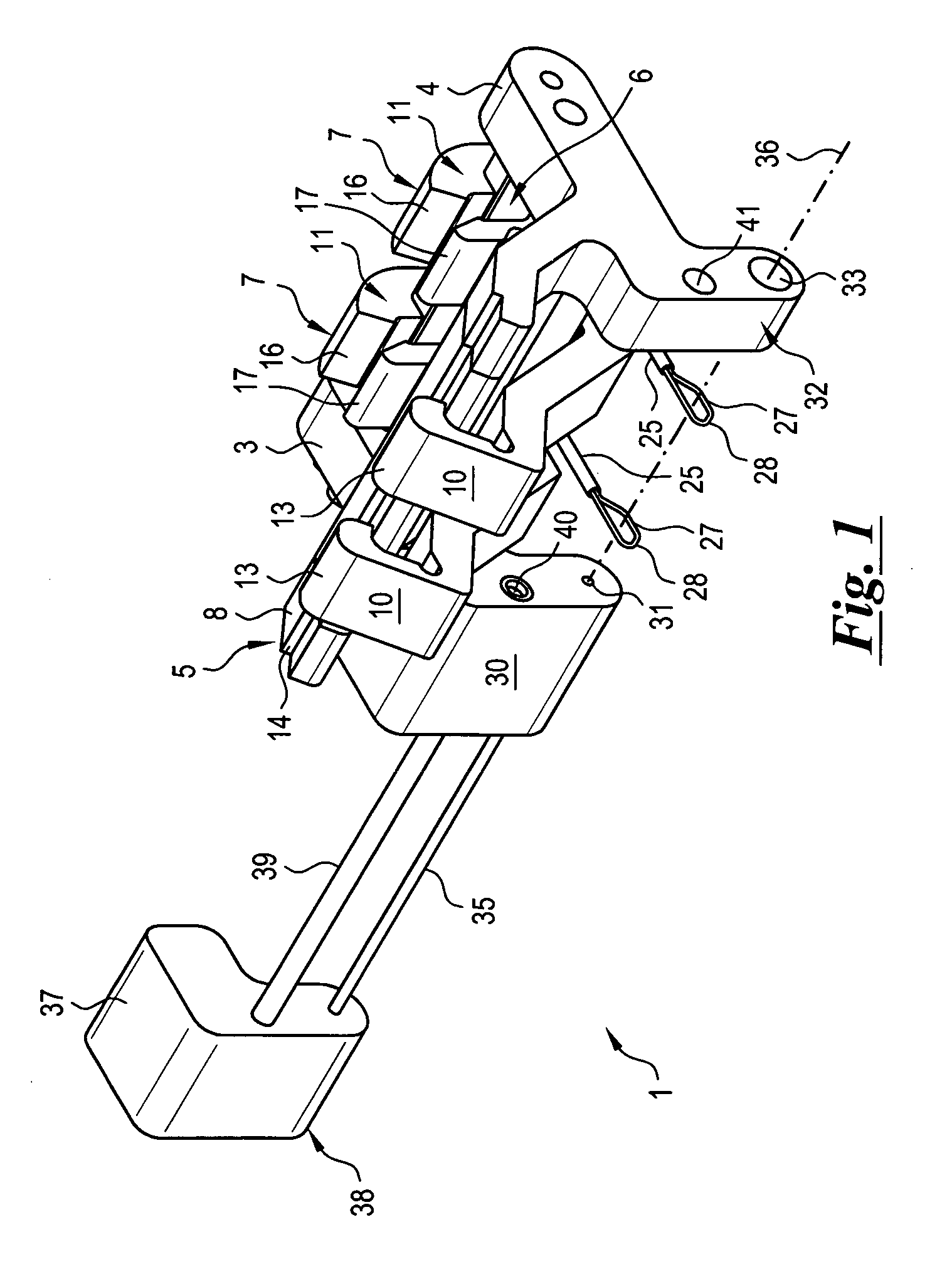
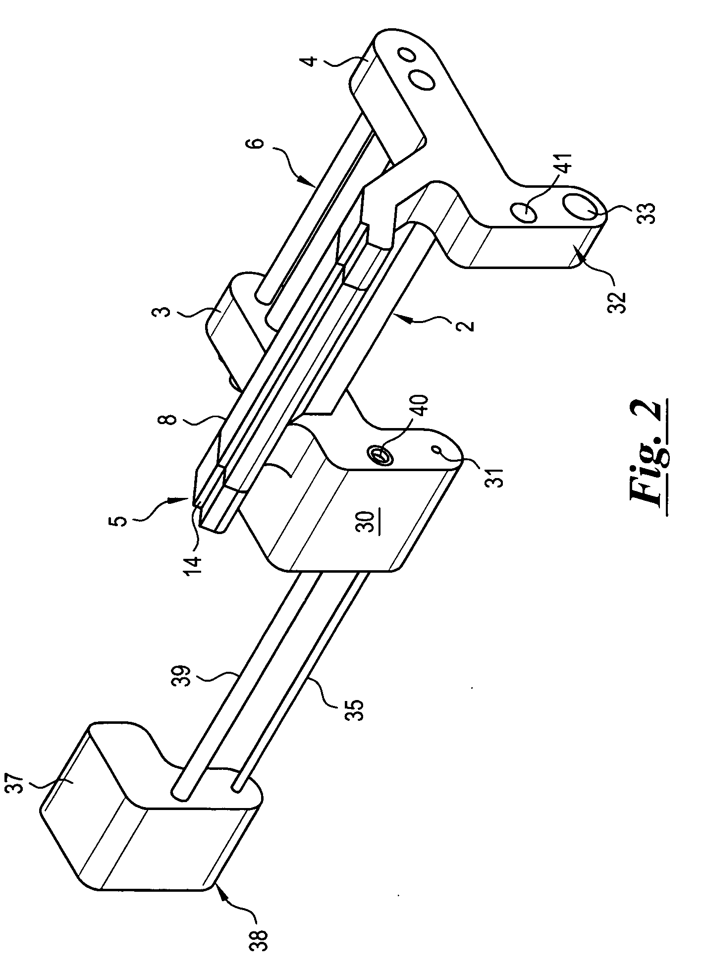
[0050]FIG. 1 shows a preferred device 1 for the insertion of a suture as will be described more fully below. As is further illustrated in FIG. 2, the device 1 generally includes a body 2 attached to and extending between a pair of arms 3, 4 associated with opposing ends of the body 2.

[0051]A first alignment member 5 projects from the body 2, and cooperates with the body 2 to provide the resulting fixture with suitable rigidity and structural support. The alignment member 5 preferably cooperates with a second alignment member 6 to form a slide for adjustably receiving one or more housings 7. In addition to receiving the housings 7, the second alignment member 6 also provides the fixture with additional rigidity and structural support.

[0052]In the preferred embodiment illustrated, the alignment member 5 terminates in a flange 8 which extends fully along the alignment member 5. The alignment member 6 preferably takes the form of a rod extending between the arms 3, 4, and which defines ...


PUM


Abstract

A suture insertion device is provided for positioning a suture inside a layer of subcutaneous tissue from a remote access point. A tether insertion device is provided for positioning a tether within subcutaneous tissue for operating on the suture from a remote access point. The suture insertion device and the tether insertion device cooperate to form the suture into a tissue-supporting sling useful for performing various surgical procedures, including but not limited to plastic surgery such as mid face lifts, neck lifts, brow lifts, under eye lifts, breast lifts, and organ repositioning.

Description

RELATED CASES[0001]This application is a continuation-in-part of prior, copending International Application No. PCT / US2008 / 009012, which designates the United States, having an International Filing Date of Jul. 25, 2008. International Application No. PCT / US2008 / 009012 claims the benefit and priority of U.S. Provisional Application No. 60 / 962,031, filed on Jul. 26, 2007. The subject matter of both International Application No. PCT / US2008 / 009012 and U.S. Provisional Application No. 60 / 962,031 is incorporated by reference as if fully set forth herein.BACKGROUND OF THE INVENTION[0002]The present invention relates to an apparatus capable of enabling a practitioner to thread a suture in a layer of subcutaneous tissue from a remote access point, to surgical methods facilitated by such an apparatus, and to associated tools useful with the apparatus for performing such surgical methods.[0003]Various surgical methods, primarily in the field of plastic surgery, require the placement of a sutur...

Claims


Application Information

Patent Timeline
IPC IPC(8): A61B17/04
CPCA61B17/0482A61B2017/00792A61B2017/06176A61B2017/06052A61B2017/0496A61B17/0485A61B17/0401A61B17/0491A61B17/06166A61B17/0469
Inventor LEVINE, DAVID E.LEVINE, DANIEL S.LEVINE, MARSHALL S.COHEN, NEAL B.
Owner ALPHA SCIENT
Why Eureka
Try Eureka