Posterior lumbar joint prosthesis

a lumbar joint and prosthesis technology, applied in the field of posterior lumbar joint prosthesis, can solve the problems of limiting mobility to some extent, generating friction on degenerated joint facets, and complete disappearance of cartilag

Active Publication Date: 2009-08-27
CLARIANCE SAS
View PDF21 Cites 42 Cited by
  • Summary
  • Abstract
  • Description
  • Claims
  • Application Information

AI Technical Summary

Benefits of technology

[0009]In a broad aspect, there is provided a posterior lumbar joint prosthesis which includes prosthetic elements reproducing the movements of the joint facets and vertebral anchors which adapt to the variations in the anatomy of vertebrae. In one embodiment, such prosthesis provides for a simple and intuitive installation by the surgeon.

Problems solved by technology

Degeneration of the vertebral joints may lead to arthrosis (osteoarthritis) of the facets that may manifest itself as a reduction in cartilage thickness, which may lead to the complete disappearance of the cartilage and thus generate friction on degenerated joint facets.
Such protrusions are largely responsible for limitations in joint motion and can also cause pain.
However, this device does not permit mobility of each member relative to the respective pedicular anchors thus limiting mobility to some extent.
However, the goal of such a device is not to replace degenerated anatomical structures while facilitating motion, but rather to stabilize and control abnormal spinal motion.
Known devices present certain disadvantages regarding, for instance but not limited to, obstruction, kinematics, mobility, friction, positioning and / or the quality of the anchors.
It is difficult, for instance, to ensure that the anchors be of a uniform quality in terms of positioning and strength due to variations in form from one vertebra to another and / or between one patient and another.
These difficulties may not only lead to bad kinematics of movement but also to degradation of the functional unit (two adjacent vertebrae).

Method used


Image

  • Posterior lumbar joint prosthesis
  • Posterior lumbar joint prosthesis
  • Posterior lumbar joint prosthesis

Examples


Embodiment Construction

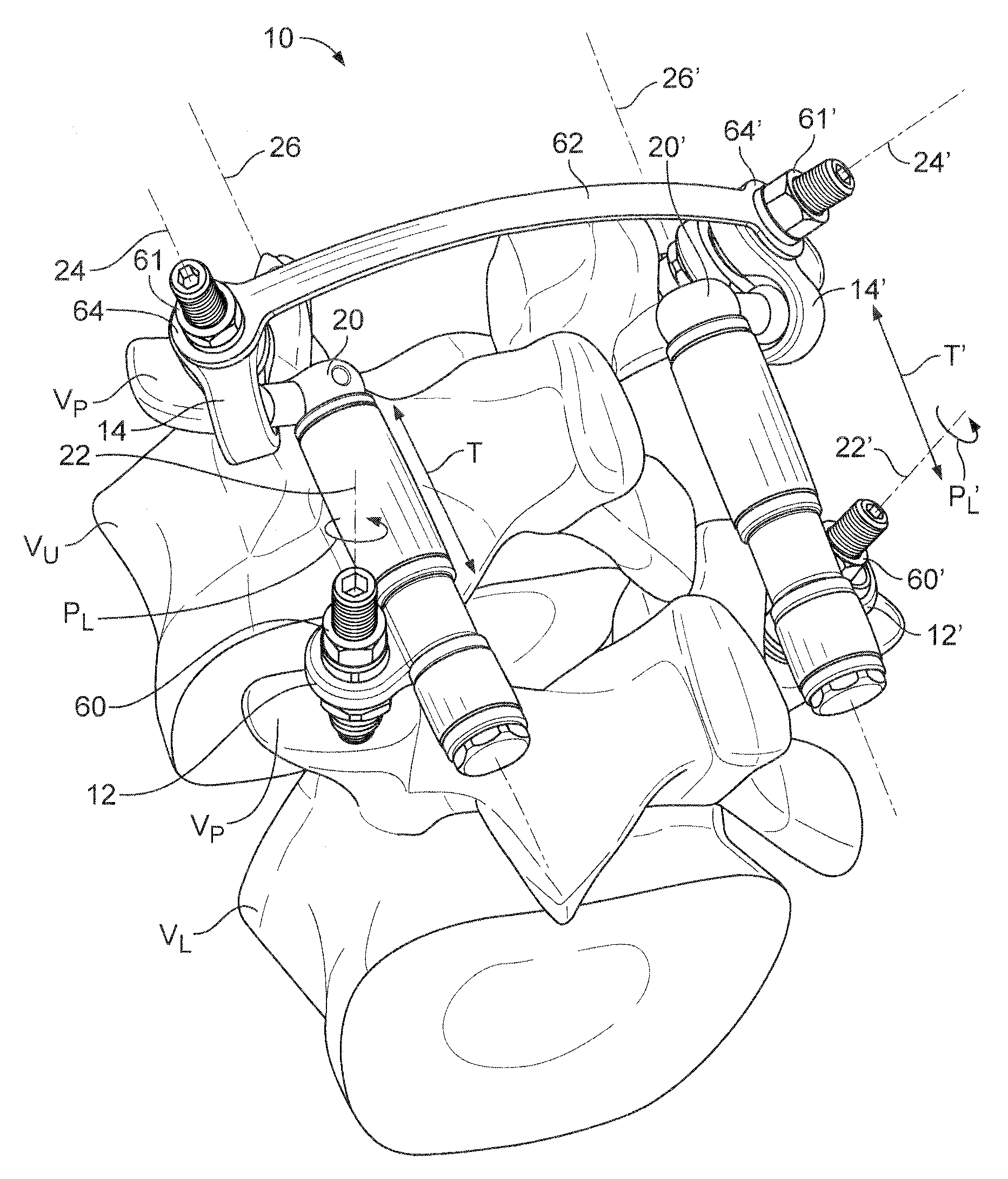
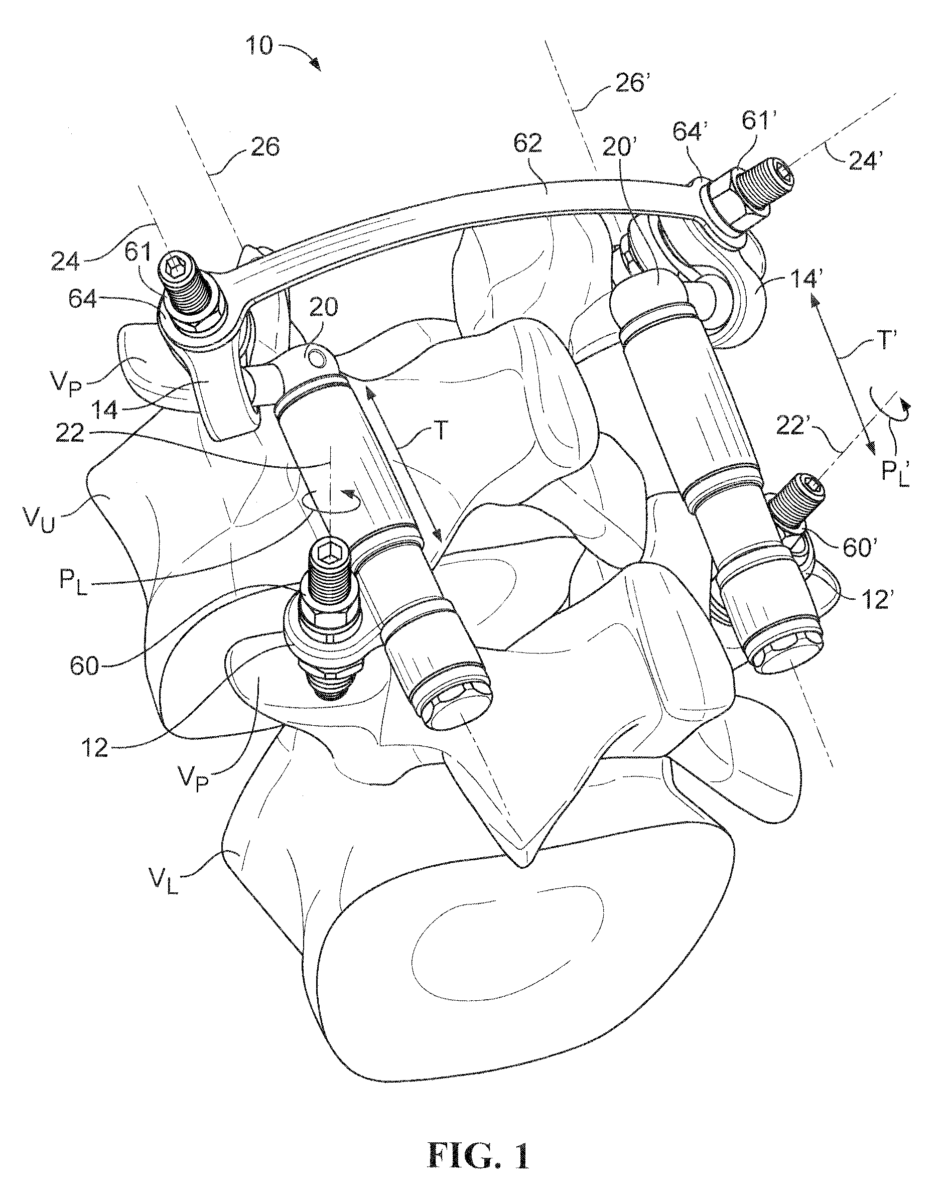
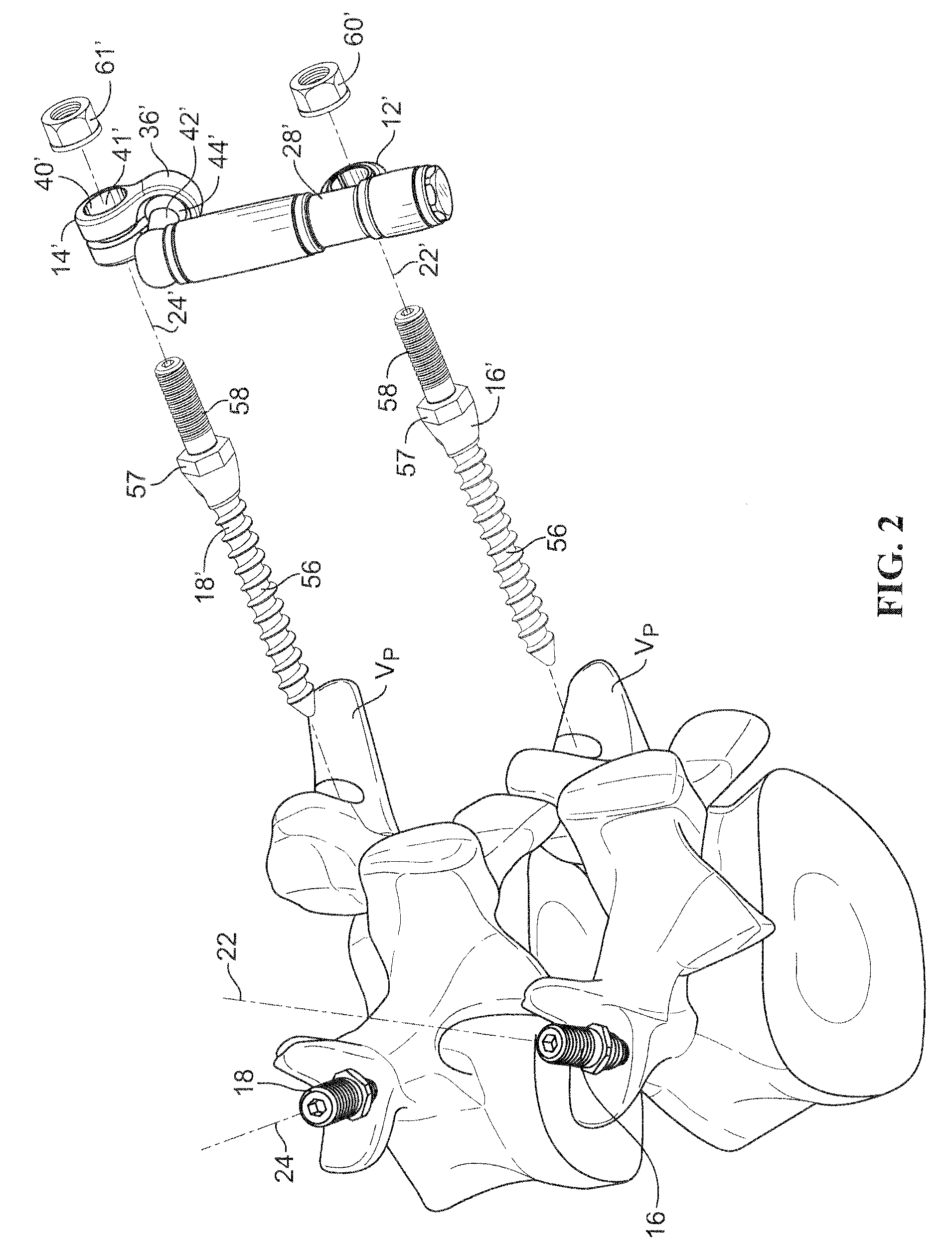
[0027]To facilitate the description, any reference numeral designating an element in one figure will designate the same element if used in any other figures. In describing the embodiments, specific terminology is resorted to for the sake of clarity but the invention is not intended to be limited to the specific terms so selected, and it is understood that each specific term comprises all equivalents.

[0028]Unless otherwise indicated, the drawings are intended to be read together with the specification, and are to be considered a portion of the entire written description of this invention. As used in the following description, the terms “horizontal”, “vertical”, “left”, “right”, “up”, “down” and the like, as well as adjectival and adverbial derivatives thereof (e.g., “horizontally”, “rightwardly”, “upwardly”, “radially”, etc.), simply refer to the orientation of the illustrated structure as the particular drawing figure faces the reader. Similarly, the terms “inwardly,”“outwardly” and...


PUM


Abstract

There is provided a posterior lumbar joint prosthesis which includes prosthetic elements reproducing the movements of the joint facets and vertebral anchors which adapt to the variations in the anatomy of vertebra. In use, the prosthesis has lower and upper connectors on each side of the lumbar vertebra. The lower connectors are coupled with, and pivotably mounted onto, respective lower pedicular screws, and a member defining a member axis links lower and upper connectors on each side of the lumbar vertebra. Upon lateral flexion of one of the upper and lower vertebrae relative to the other, each lower connector is capable of multiaxis pivotable movement relative to the respective lower pedicular screws such that each member is capable to pivot with respect to (i) the axis of the lower screw, (ii) a first axis intersecting the lower screw and the lower connector, and / or (iii) an axis intersecting the above first axis and the lower screw, while the member can also move along the member axis.

Description

CROSS-REFERENCE TO RELATED APPLICATIONS[0001]This application claims the benefit of U.S. Provisional Patent Application 61 / 033,040, filed on Mar. 3, 2008 and of French patent application Ser. No. 08 / 01020, filed on Feb. 26, 2008, the contents of which are incorporated herein by reference in their entirety.FIELD OF THE INVENTION[0002]The present invention relates to a posterior lumbar joint prosthesis allowing flexing and extension movements, lateral flexion, and rotation concomitant with lateral flexion of the upper and lower lumbar vertebrae.BACKGROUND OF THE INVENTION[0003]Degeneration of the vertebral joints may lead to arthrosis (osteoarthritis) of the facets that may manifest itself as a reduction in cartilage thickness, which may lead to the complete disappearance of the cartilage and thus generate friction on degenerated joint facets. Osteophytes which are protrusions of bone and cartilage are very common and develop in areas of a degenerating joint as a reparative response b...

Claims


Application Information

Patent Timeline
Patent Type & Authority Applications(United States)
IPC IPC(8): A61B17/70A61B17/86
CPCA61B17/7011A61B17/7023A61B17/7025A61F2/4405A61B17/7035A61B17/7041A61B17/7064A61B17/7032A61B17/702A61B17/7043
Inventor TORNIER, ALAINSTEIB, JEAN-PAULMAZEL, CHRISTIAN
Owner CLARIANCE SAS
Why Eureka
Try Eureka