Cable Retention Device

a technology of retaining device and cable, which is applied in the direction of cable arrangement between relatively moving parts, machine supports, other domestic objects, etc., can solve the problems of greater risk of cable damage and relatively low risk of cable damage, and achieve the effect of simple devices to take and force costs being kept relatively low

Inactive Publication Date: 2009-09-03
ROXTEC AB
View PDF3 Cites 71 Cited by
  • Summary
  • Abstract
  • Description
  • Claims
  • Application Information

AI Technical Summary

Benefits of technology

[0008]One object of the present invention is that forces exerted by or on a cable in any direction should be taken up. A further object is that relatively simple and yet reliable devices should be used to take up the forces. By having relatively simple devices to take up the forces costs can be kept relatively low. A further object is that

Problems solved by technology

At the same time there is a firm contact between a cable and a module, due to high friction in said contact.
Furthermore, due to the elasticity of the modules the risk of damage to the cables is

Method used


Image

  • Cable Retention Device
  • Cable Retention Device
  • Cable Retention Device

Examples


Embodiment Construction

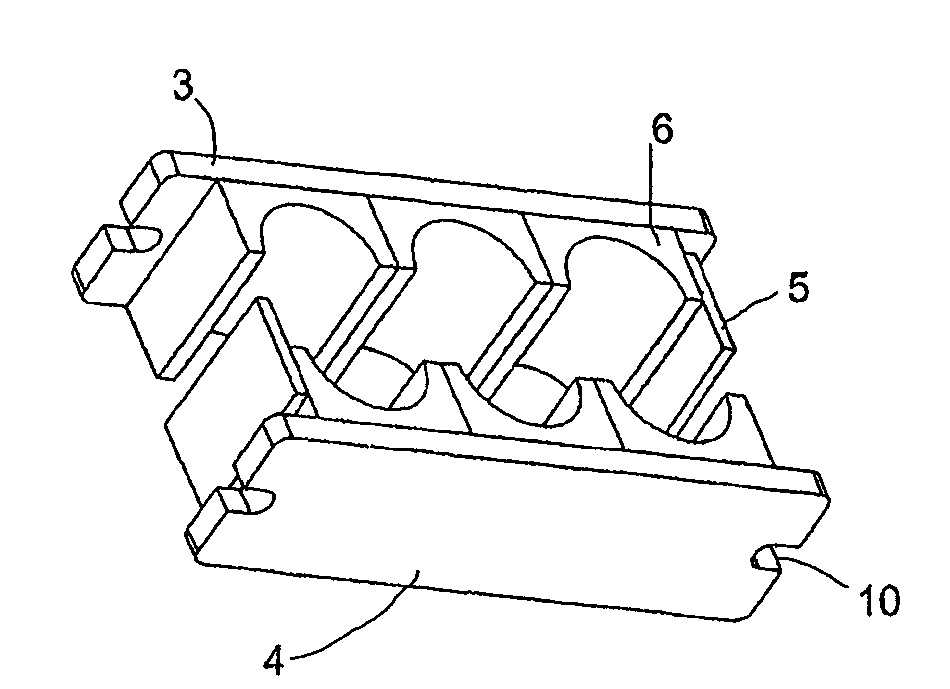
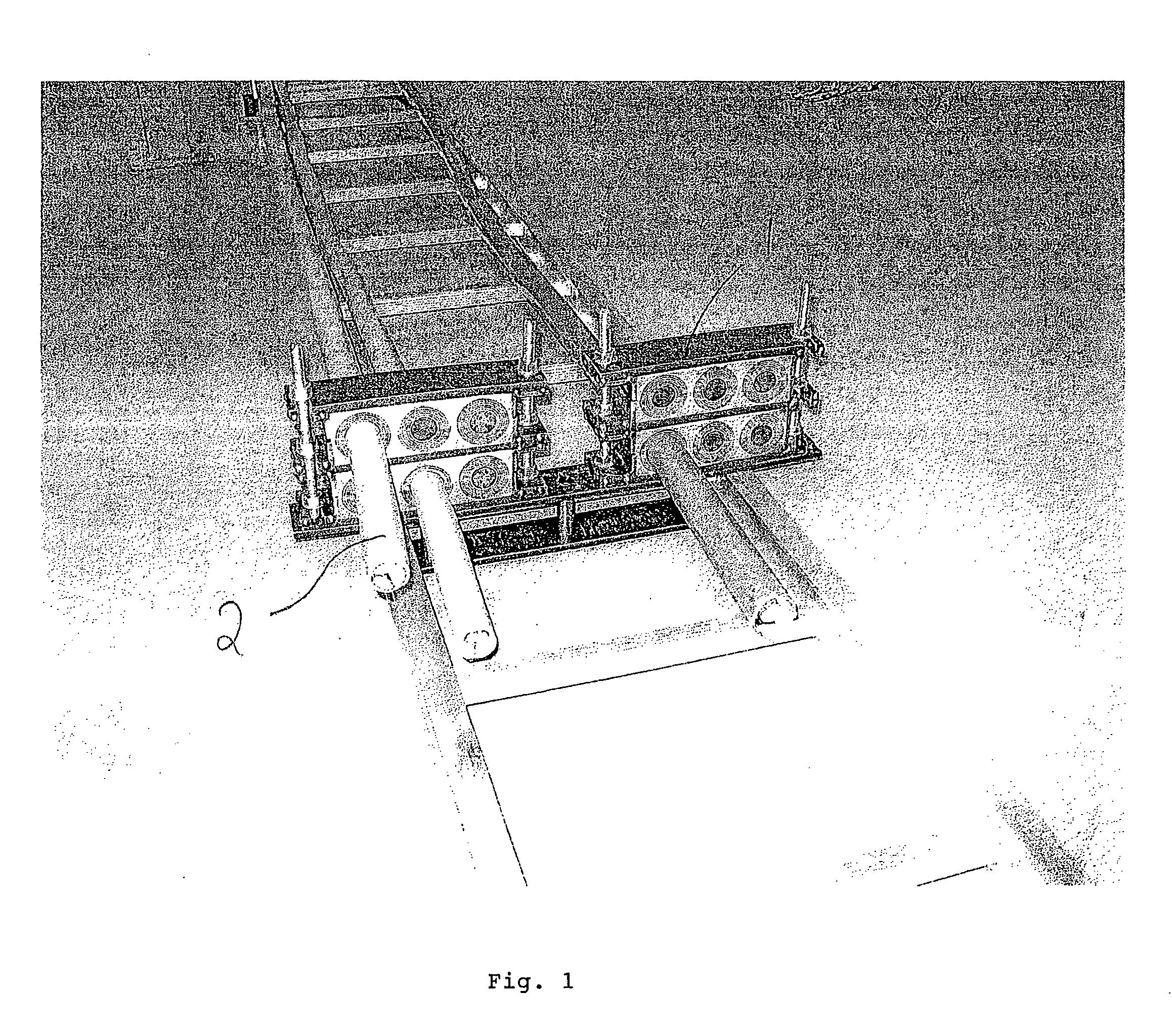
[0037]In the embodiment of FIG. 1 two frame constructions 1 are shown, inside which a number of modules are received. The modules are to receive a cable 2 each. In the shown example one of the frames receive one cable 2 and the other frame two cables 2. The number of cables received in each frame 1 may vary and normally most of the modules will have a cable 2. In the various examples below cable retention devices are shown having different numbers of columns and receiving different numbers of modules. A person skilled in the art realises that the numbers of columns and modules may vary as well as the dimensions of the columns and modules. However, the dimensions of co-operating modules and columns are adapted to each other.

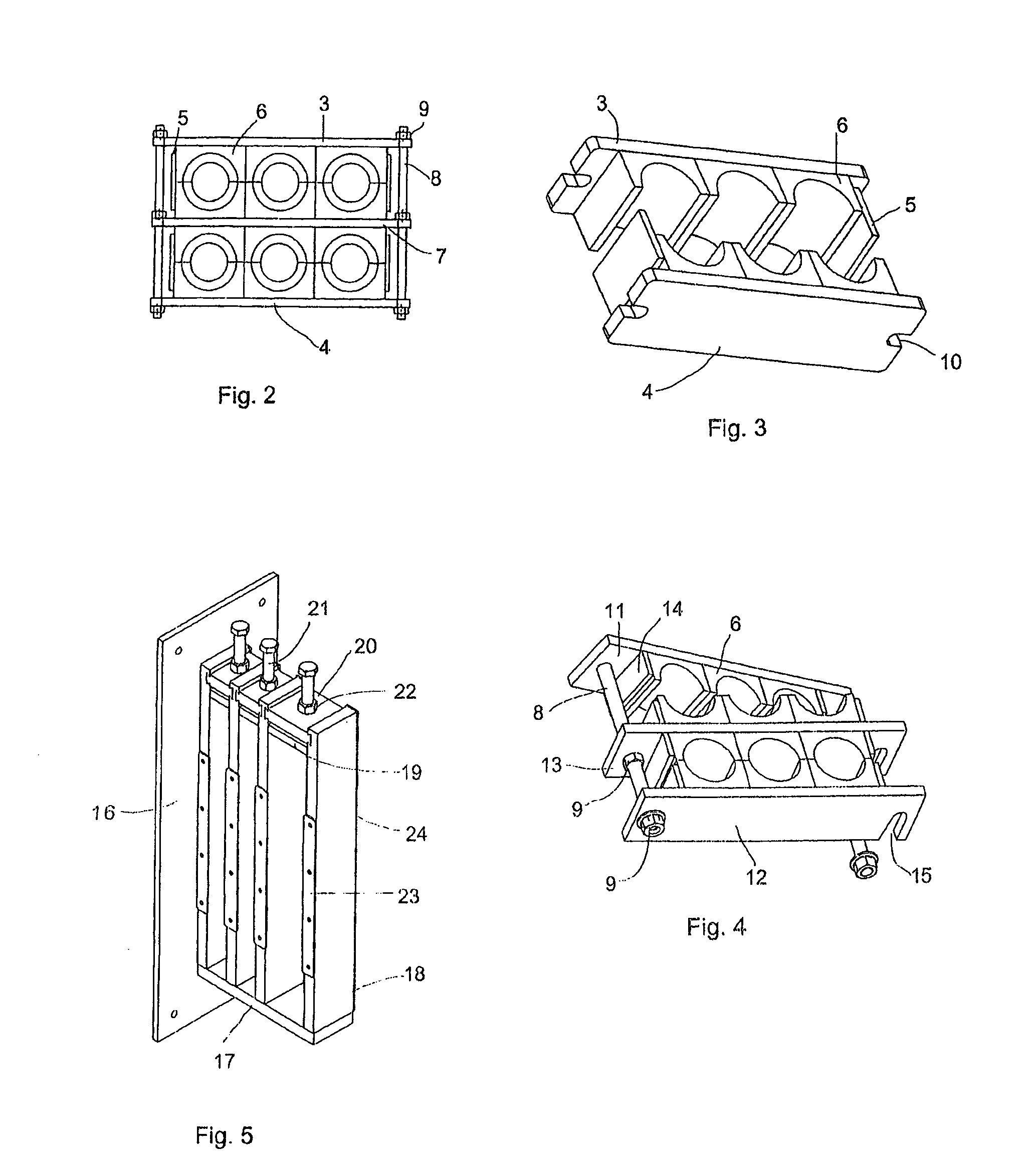
[0038]Each frame construction 1 comprises a number of plates 3, 4, 7 placed aligned one over the other. Thus, there will one outer plate 3, 4 at each end and a number of intermediate plates 7. In the shown example of FIGS. 1 and 2 there is only one intermediate pl...


PUM


Abstract

The present invention concerns a cable retention device, which also may be used for pipes or wires, to take up forces actuated by or on a cable (2) etc. Each cable (2) is received in a module, formed of two module halves (6, 55, 58, 62). The modules are received inside a rigid frame construction. The modules inside the frame construction are to be compressed. The compression is accomplished by means of a compression unit (36, 41) inside the frame construction and/or by assembly of the cable retention device.

Description

TECHNICAL FIELD[0001]The present invention concerns a cable retention device to hold one or more cables and take up forces exerted by or on the one or more cables.PRIOR ART[0002]In many contexts where cables are used the cables are exerted to relatively large forces. Often such forces has to be taken up to not harm the cables or apparatuses or the like receiving the cables. The forces exerted on the cables may be gravity, torsion (rotational), traction, pulling, “whiplash” (caused by e.g. short circuited cables) and / or vibration forces.[0003]It is common to use different types of cable clamps, but ordinary cable clamps will not take up any forces. Thus, there is a high risk that the cables are harmed if exerted to relatively high forces and if the cable clamps do not yield in any substantial way. One problem being that there is no real elastic connection between the cable and a structure receiving the cable clamps.[0004]In wind power stations (plants) the turbine and its wings are u...

Claims


Application Information

Patent Timeline
IPC IPC(8): F16L3/08
CPCF16L5/02H02G11/00H02G3/30F16L5/14F16L5/08H02G3/22H02G15/007
Inventor LUNDBORG, CHRISTER
Owner ROXTEC AB
Why Eureka
Try Eureka