
Image Capture Device

Inactive Publication Date: 2009-09-03
FUNAI ELECTRIC CO LTD
View PDF8 Cites 0 Cited by
  • Summary
  • Abstract
  • Description
  • Claims
  • Application Information

AI Technical Summary

Benefits of technology

[0013]An object of the present invention is to provide an image capture device which, with reduced cost and improved design, allows a user to clearly observe an image while captured even if the user is presbyopic, and which can prevent degradation in the quality of the observed image.
[0015]According to the image capture device of the present invention having the structure described above, a user can observe an image (while captured) displayed on the display as a real image by directly seeing the display. The user can also observe the image on the display through the viewing opening of the camera body as a virtual image produced by the virtual image optical system by putting an eye to the camera body and looking into the viewing opening. In other words, the user, if normally sighted, can clearly observe an image, while captured, by directly seeing the display. If the user is presbyopic, the user can also clearly observe an image, while captured, through the viewing opening of the camera body. The image capture device thus has improved convenience of use.
[0016]Furthermore, the image capture device is designed so that the virtual image optical system produces a virtual image of an image displayed on the display, so as to allow the user to observe the virtual image through the viewing opening. Thus, it is not necessary to separately provide e.g. an image display element in the camera body, thereby preventing an increase in cost. In addition, the virtual image optical system is designed to allow the user to observe the virtual image through the viewing opening (i.e. by putting an eye to the camera body), so that the virtual image optical system can be small in size, thereby reducing the size of the image capture device. Further, since the virtual image optical system is contained in the camera body, the image capture device can have an improved design. Besides, the provision of the virtual image optical system inside the camera body makes it possible to prevent the hand of the user from touching the virtual image optical system, thereby preventing the virtual image optical system from being stained or damaged, and also preventing degradation in the quality of the image observed through the viewing opening. In summary, the image capture device of the present invention has reduced cost and improved design, and allows a user to clearly observe an image while captured even if the user is presbyopic, and further can prevent degradation in the quality of the observed image.
[0017]Preferably, the display can be positioned in a first opened position as the opened position to expose the image display surface where the image display surface is exposed and substantially perpendicular to a direction for the camera body to capture an image. When the display is in the first opened position, the virtual image optical system and the viewing opening are positioned outside a rectangular space which is formed by indefinitely extending the image display surface in a direction perpendicular thereto. This is preferable because when the user directly sees the display with the display brought to the first opened position, the view of the user is not blocked by the virtual image optical system and the viewing opening, thereby allowing the user to easily observe an image while captured, and easily capture an image, improving convenience of use.
[0018]Further preferably, the virtual image optical system produces the virtual image so as to allow the user to observe the virtual image in a direction parallel to the direction for the camera body to capture the image. This is preferable because when the user observes an image, while captured, through the viewing opening of the camera body, the direction of the line of sight of the user (image observation direction by the user) is parallel to the image capture direction, so that the user can easily capture the image, thereby improving convenience of use.
[0021]Still further preferably, the image capture device further comprises notifying means for notifying that the image capture device is in a state in which the virtual image can be observed through the viewing opening. This is preferable because without actually seeing through the viewing opening, the user can recognize whether the image capture device is in a state in which the image while captured can be observed through the viewing opening, thereby improving convenience of use.

Problems solved by technology

However, each of the image capture devices 70 and 80 described above has drawbacks in that when a user observes an image, while captured, by seeing the display 72, the user may find it difficult to clearly observe an image while captured if, for example, the user is presbyopic (farsighted) because the observation distance from the eye of the user to the display 72 is too short.
However, this increases the cost because it requires an image display element for ocular observation.
Thus, the image capture device does not have a good design because the enlarging lens set is placed outside the camera body, and also because the enlarging lens set is relatively large.
In addition, the placement of the enlarging lens set outside the camera body may cause the user to contact the enlarging lens set by hand, thereby staining or damaging the enlarging lens set, which in turn may degrade the quality of the image observed through the enlarging lens set.
However, none of these known devices in the relevant art can solve the problems described above.

Method used


Image

  • Image Capture Device
  • Image Capture Device
  • Image Capture Device

Examples


first embodiment

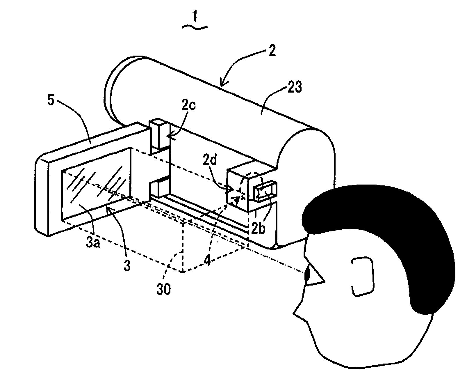
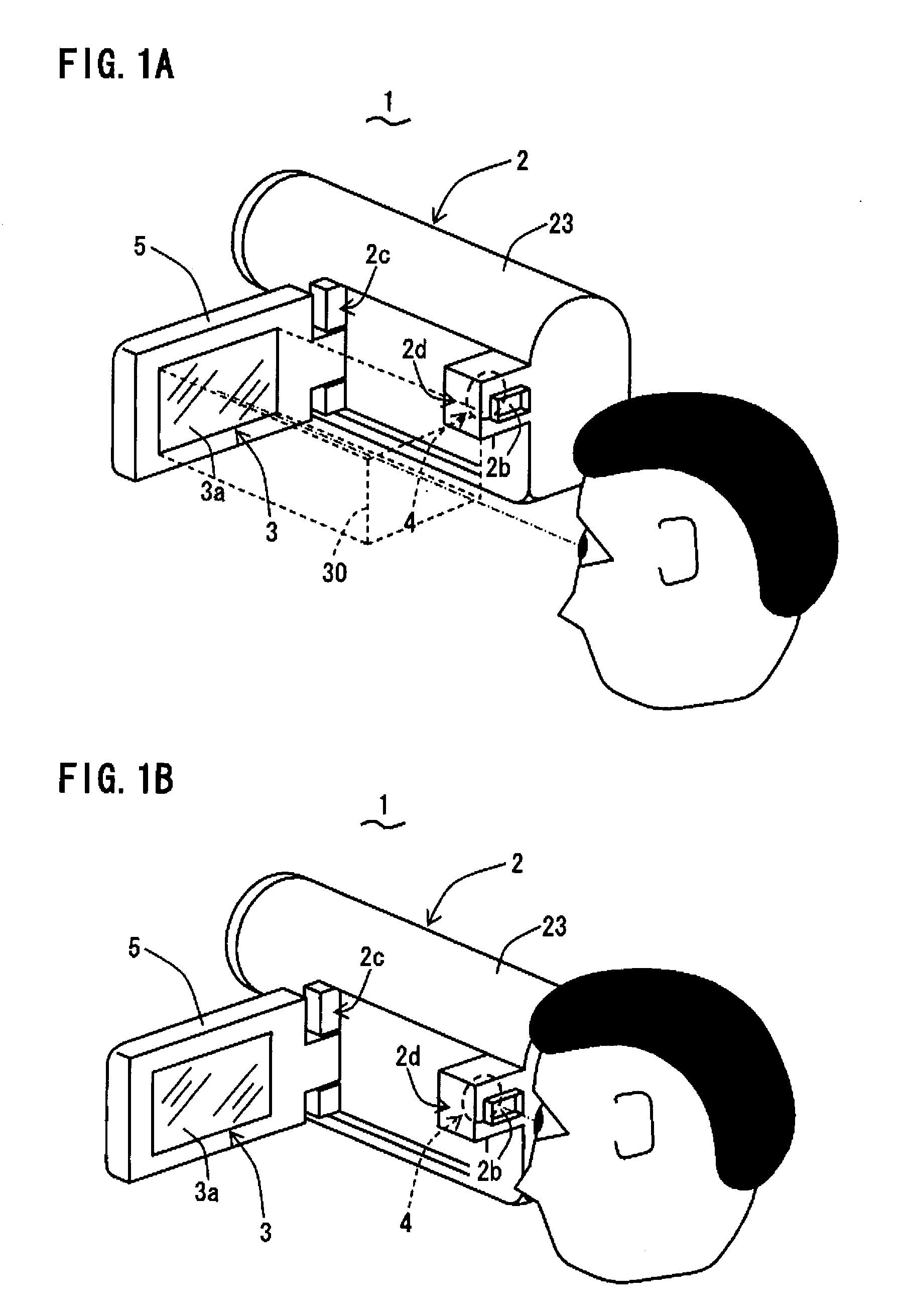
[0034]Referring to FIGS. 1A and 1B and FIG. 2, an image capture device 1 according to a first embodiment of the present invention will be described.

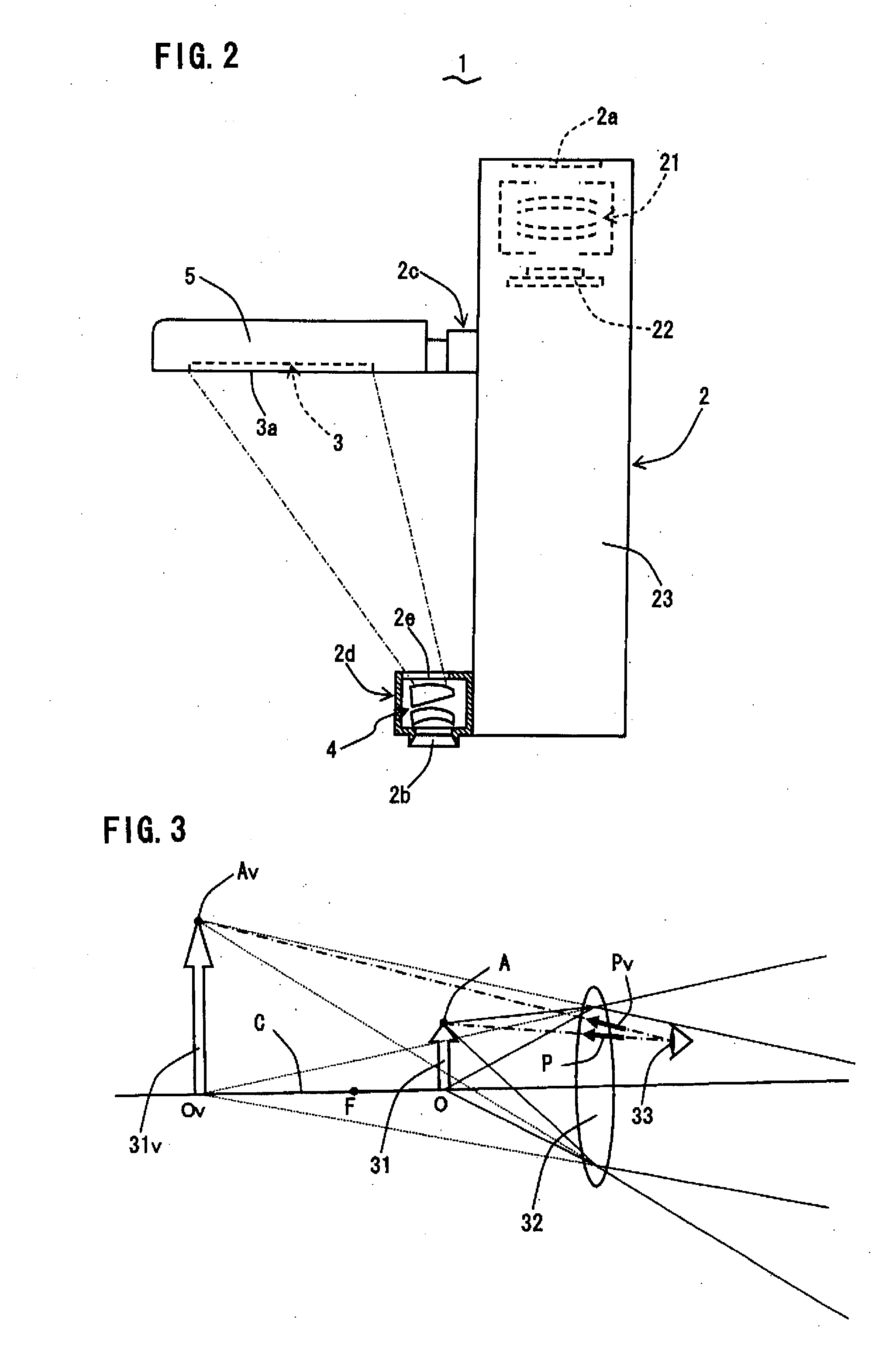
[0035]FIG. 1A is a schematic perspective view of an image capture device 1 according to the first embodiment when a user directly sees a display 3 which is in a first opened position, while FIG. 1B is a schematic perspective view of the image capture device 1 when the user looks into a viewing opening 2b. On the other hand, FIG. 2 is a schematic top plan view, partially in cross section, of the image capture device 1 when the display 3 is in the first opened position. The image capture device 1 optically captures a target object, and converts an optical image of the target object, thus captured, to image data of an electric signal so as to capture the image of the target object. The image capture device 1 is designed so that a user can hold it in hand for image capture, and can observe an image while captured.

[0036]The image capture devi...

second embodiment

[0052]Referring now to FIGS. 4A and 4B and FIG. 5, an image capture device 1 according to a second embodiment of the present invention will be described. FIG. 4A is a schematic perspective view of an image capture device 1 according to the second embodiment when a user directly sees a display 3 which is in a first opened position, while FIG. 4B is a schematic perspective view of the image capture device 1 when the display 3 is in a second opened position, and the user looks into a viewing opening 2b. On the other hand, FIG. 5 is a schematic top plan view, partially in cross section, of the image capture device 1 when the display 3 is in the second opened position. The image capture device 1 of the second embodiment is designed so that by pivoting a lid member 5, a display 3 can be brought to two opened positions where an image display surface 3a is exposed: not only a first opened position (where the image display surface 3a is exposed and substantially perpendicular to the directio...


PUM


Abstract

An image capture device comprises a camera body held by a user for capturing an image, a display for displaying an image while captured, and a virtual image optical system for producing a virtual image of the image displayed on the display. The display is openably / closably supported by the camera body and positioned in opened / closed positions to expose or unexpose an image display surface. The optical system is contained in the camera body to produce a virtual image of the image on the display to allow the user to observe the virtual image through a viewing opening of the camera body. The user, even if presbyopic, can clearly observe an image, while captured, through the viewing opening. This device has reduced cost and improved design, and allows a user, even if presbyopic, to clearly observe an image while captured, and can prevent degradation in the quality of the observed image.

Description

BACKGROUND OF THE INVENTION[0001]1. Field of the Invention[0002]The present invention relates to an image capture device for capturing an image.[0003]2. Description of the Related Art[0004]An image capture device is known which can be held by a hand of a user to capture an image, and which allows the user to observe an image while captured. FIGS. 7 and 8 each show an example of such an image capture device. FIG. 7 shows an image capture device 70 comprising a camera body 71 to be held by a hand of a user for capturing an image of a target object, and a display 72 for displaying an image while captured by the camera body 71. The camera body 71 has built therein e.g. an optical system and a photoelectric conversion element (not shown) for image capture. The photoelectric conversion element converts an optical image captured by the optical system to image data of an electric signal so as to capture the image. Based on the image data obtained from the photoelectric conversion element, t...

Claims


Application Information

Patent Timeline
IPC IPC(8): H04N5/222
CPCH04N5/23293H04N23/531
Inventor ISHIBASHI, KENJI
Owner FUNAI ELECTRIC CO LTD
Features
  • Generate Ideas
  • Intellectual Property
  • Life Sciences
  • Materials
  • Tech Scout
  • Unparalleled Data Quality
  • Higher Quality Content
  • 60% Fewer Hallucinations
Learn More