Tide apparatus and tide structure

a technology of tide apparatus and structure, which is applied in the direction of piers, groynes, breakwaters, etc., can solve the problems of inconvenient use of the building, inability to install tide plates, and futile installation of tide plates, so as to reliably keep back water and ensure the effect of water retention

Inactive Publication Date: 2009-09-03
SPACETECH
View PDF13 Cites 15 Cited by
  • Summary
  • Abstract
  • Description
  • Claims
  • Application Information

AI Technical Summary

Benefits of technology

[0119]By the present invention, the tide plate can be automatically installed in order to reliably keep back water in overhead flooding or the like without depending on power such as human power and electricity, and the tide plate can be installed in advance in order to reliably keep back water in overhead flooding or the like even in the case in which a large amount of water flows once and for all due to a collapse of a levee or a tsunami caused by an earthquake.
[0120]Moreover, the present invention can provide a tide apparatus in which the tide plate is not operated in the case of a normal rainfall to prevent the passage from being obstructed.
[0121]Furthermore, the present invention can provide a tide apparatus in which the tide plate that has protruded upward from the soil foundation face can be immediately pulled below the soil foundation face, thereby preventing the passage from being obstructed in the case in which a disaster occurs.

Problems solved by technology

However, in the case in which the soil foundations of a building are raised, a staircase must be formed for going in and out of the building, thereby resulting in inconvenience in utilizing the building.
Moreover, in the case in which a tide plate is installed manually, the prediction of a flood does not come true in some cases and the installation of the tide plate is futile.
In the case in which heavy rain occurs suddenly and hands are insufficient, the tide plate cannot be installed.
Unfortunately, in the case in which the tide plate is powered by electricity to be moved up and down, the tide plate does not operate by a failure or a power outage in some cases, and an installation cost becomes extremely high.

Method used


Image

  • Tide apparatus and tide structure
  • Tide apparatus and tide structure
  • Tide apparatus and tide structure

Examples


Embodiment Construction

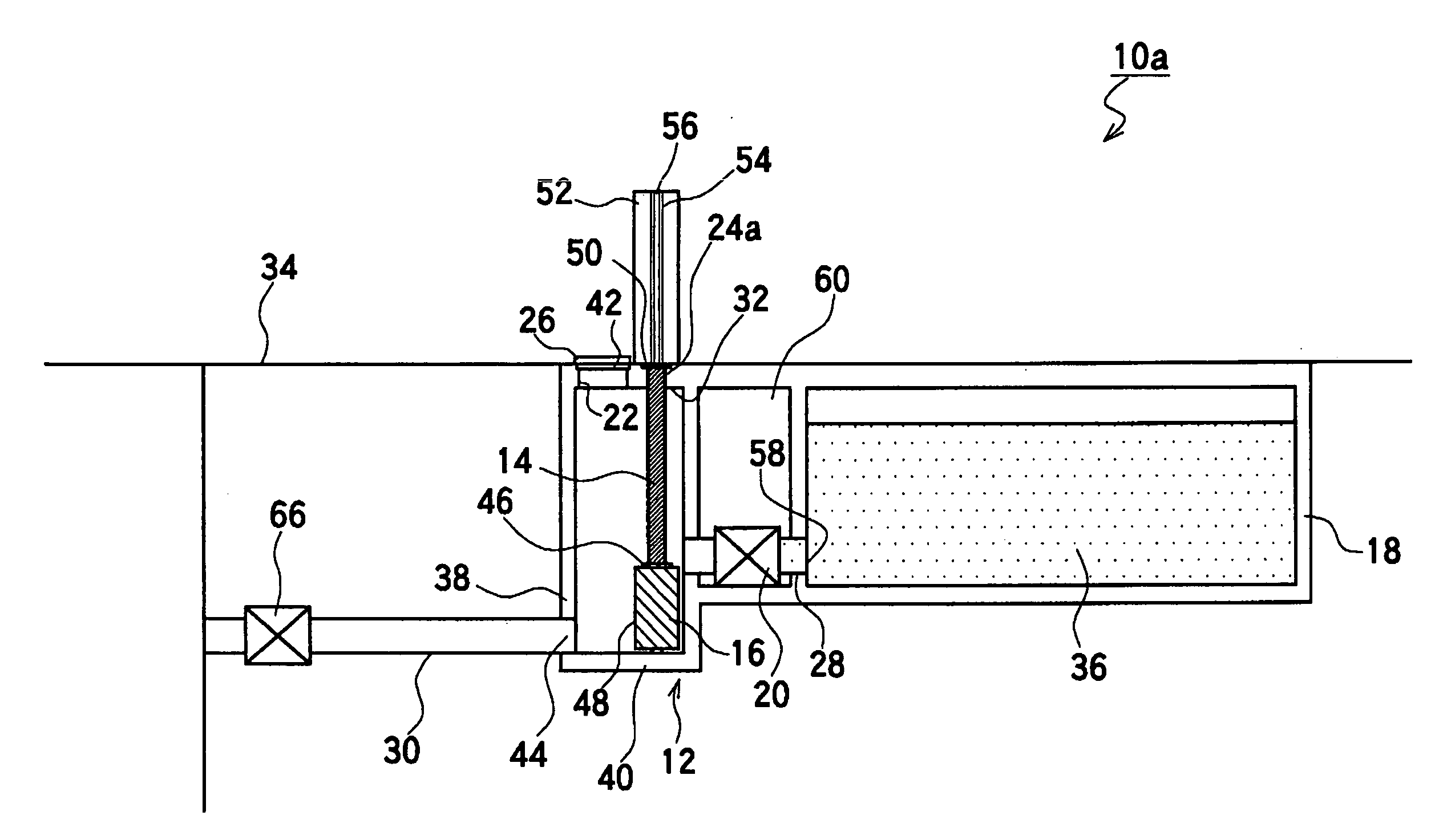
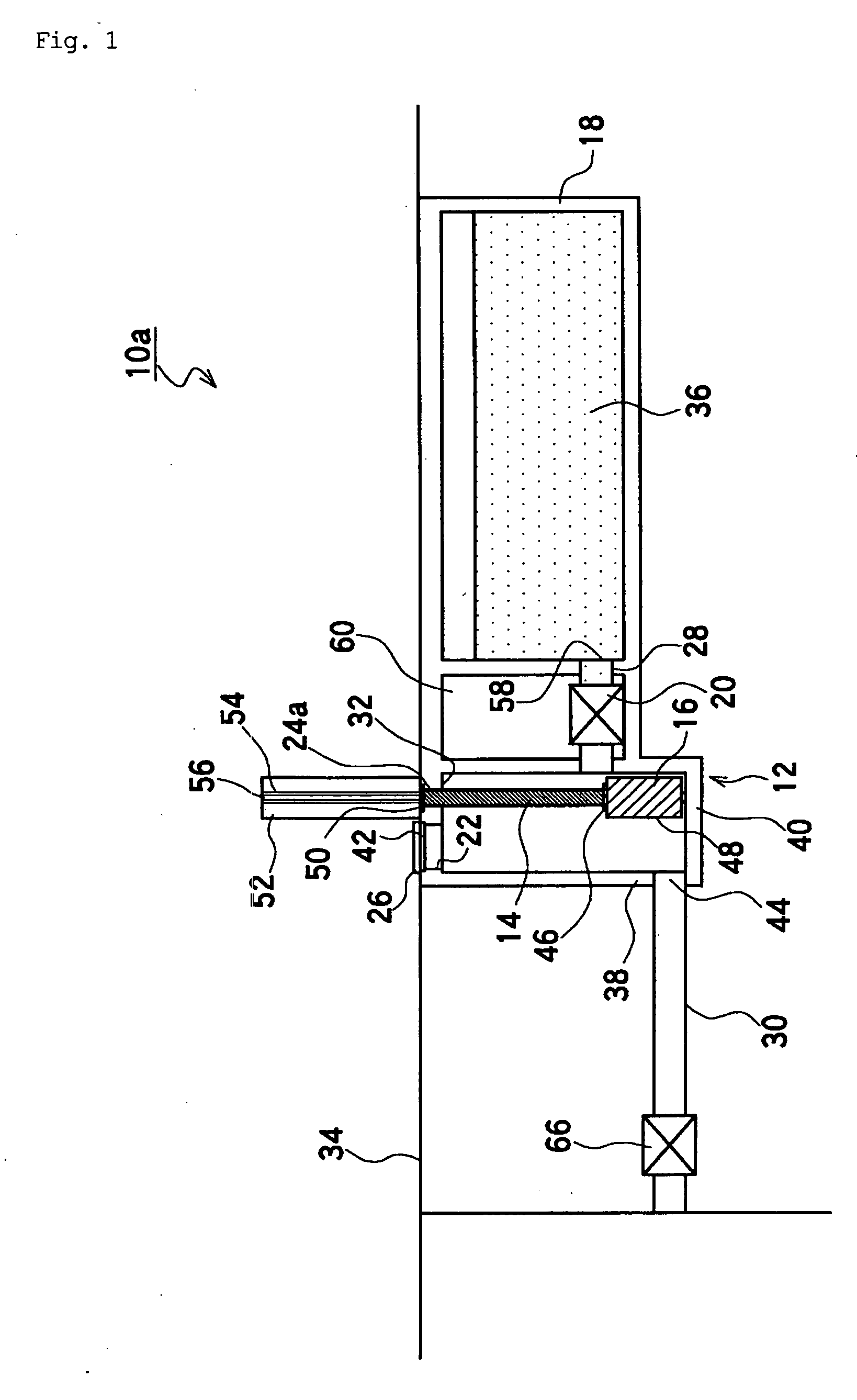
[0216]An embodiment (example) of the present invention will be described below in detail with reference to the drawings.

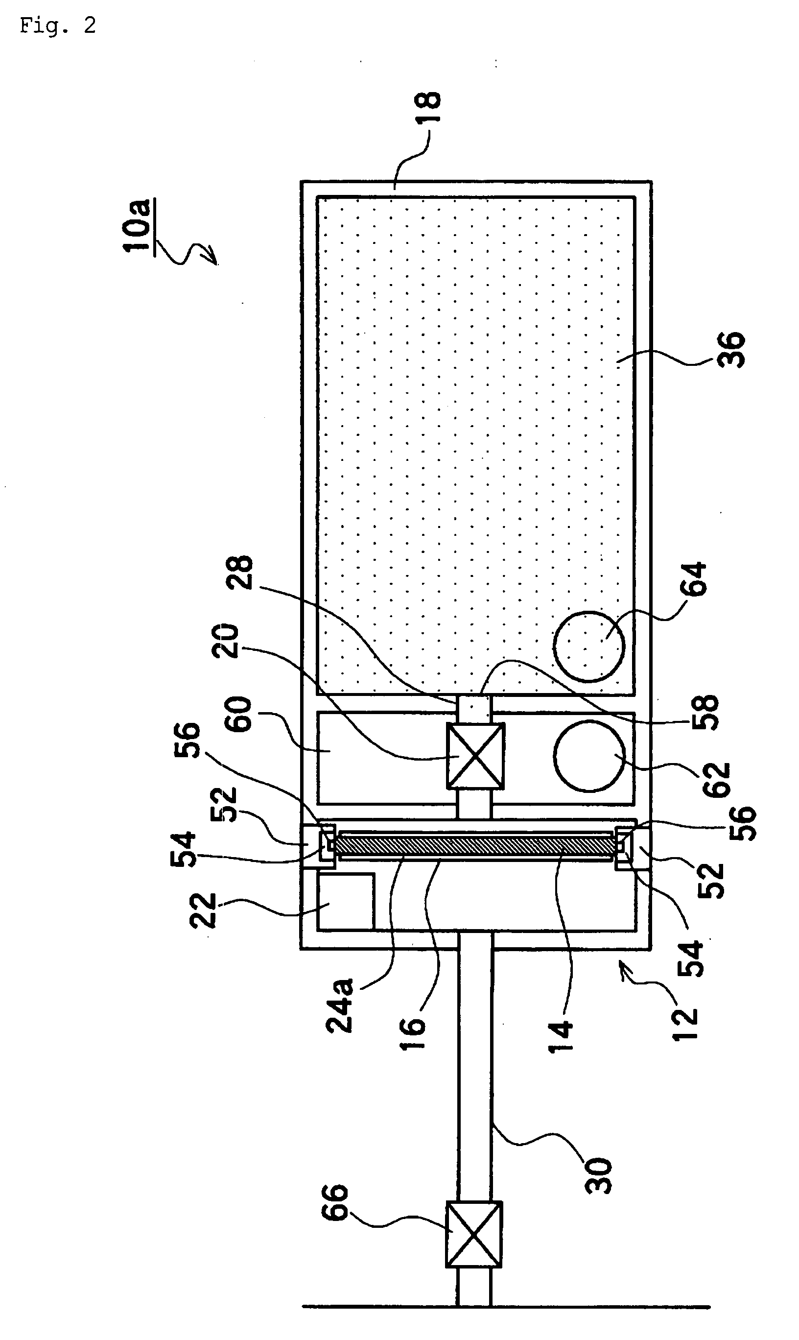
[0217]FIG. 1 is a schematic cross-sectional view showing a normal state of a first embodiment of a tide apparatus in accordance with the present invention. FIG. 2 is a top view showing the tide apparatus of FIG. 1. FIG. 3 is a schematic cross-sectional view showing a state in overhead flooding for the tide apparatus of FIG. 1. FIG. 4 is a process drawing of a first embodiment of a tide apparatus in accordance with the present invention. FIG. 5 is a schematic view showing a tide structure including the tide apparatus of FIG. 2.

[0218]A numeral 10a represents a tide apparatus as a whole.

[0219]FIG. 1 shows a first embodiment of the tide apparatus 10a in accordance with the present invention. In the figure, an underground pit 12 made of a reinforced concrete for instance is formed under a soil foundation face 34.

[0220]The underground pit 12 is formed by a ceiling wall 3...


PUM


Abstract

It is an object to provide a tide apparatus comprising a storage tank connected to a underground pit for normally storing water of a constant amount, a connecting pipe for connecting between the underground pit and the storage tank, and a seismograph releasing apparatus formed on the connecting pipe for sensing a shake in an earthquake and for releasing the water stored in the storage tank into the underground pit, wherein the tide plate can protrude upward from the soil foundation face by operating the seismograph releasing apparatus in an earthquake to make the water stored in the storage tank flow into the underground pit via the connecting pipe.

Description

TECHNICAL FIELD[0001]The present invention relates to a tide apparatus and tide structure that: are disposed around a building or a civil engineering work piece for preventing an infiltration or an outflow of water during a tsunami or a flood caused by an earthquake or the like.BACKGROUND ART[0002]For instance, in an area in which an inundation may occur due to a tsunami or a flood caused by an earthquake or the like, an infiltration or an outflow of water has been generally prevented by raising the soil foundations of a building or by building levees on the both banks of a river.[0003]Around a building in which the soil foundations cannot be raised, a tide plate is generally installed at the location in which a water flow must be cut off, and the water is kept back by the tide plate.[0004]A conventional tide plate of this kind is generally formed in any shape such as a flat plate, and is installed manually in advance at the location in which water must be kept back in the case in w...

Claims


Application Information

Patent Timeline
Patent Type & Authority Applications(United States)
IPC IPC(8): E02B3/06
CPCE02B7/28E02B7/205
Inventor MIYAO, SUSUMUBANNO, ISAOFUJITA, HIDEKI
Owner SPACETECH
Why Eureka
Try Eureka