Multi-circuit direct current monitor with Modbus serial output

a direct current monitor and multi-circuit technology, applied in the direction of instruments, pv power plants, sustainable buildings, etc., can solve the problems of not being able to provide additional information regarding any of the components of the overall solar system, affecting the output of the panel, and providing little if any useful information about the operation of the strings or arrays of the solar system

Inactive Publication Date: 2009-09-03
OBVIUS HLDG
View PDF9 Cites 36 Cited by
  • Summary
  • Abstract
  • Description
  • Claims
  • Application Information

AI Technical Summary

Problems solved by technology

These meters are used for billing purposes, but they provide little if any useful information about the operation of the strings or arrays of the solar system other than to provide a summary of the AC power output from the inverter.
The output of the panel may also be impacted on a short term basis by cloud cover, dirt, obstructions, or failure of any of the electrical components or connections.
The net meter previously described can only provide a general indication of the performance of the array, but cannot provide additional information regarding any of the components in the overall solar system.
The external environmental factors previously described can provide insight into the performance of the solar array, but they do not provide a means for locating and identifying other issues which may arise within the solar power system.
Tracking the input DC power and the output AC power (in conjunction with the weather monitoring system described previously) can help the owner / installer to identify problems that arise such as electrical failures or obstructions on the solar array as a whole, but does not provide information regarding the source of the inefficiency unless the inverter itself is at fault.
For example, dirt or debris can accumulate on the surface of the solar panel and this will greatly reduce the amount of power produced by the panel as the sunlight is prevented from reaching the solar cell.
This can be accomplished by using individual Hall Effect sensors or shunts to measure the DC current from each string, but this approach requires significant space for installation and also requires a number of additional devices and installation labor to bring each of the signals into an analog input device for communication to the data acquisition system as well as significant configuration labor to provide appropriate scaling factors.

Method used


Image

  • Multi-circuit direct current monitor with Modbus serial output
  • Multi-circuit direct current monitor with Modbus serial output
  • Multi-circuit direct current monitor with Modbus serial output

Examples


Embodiment Construction

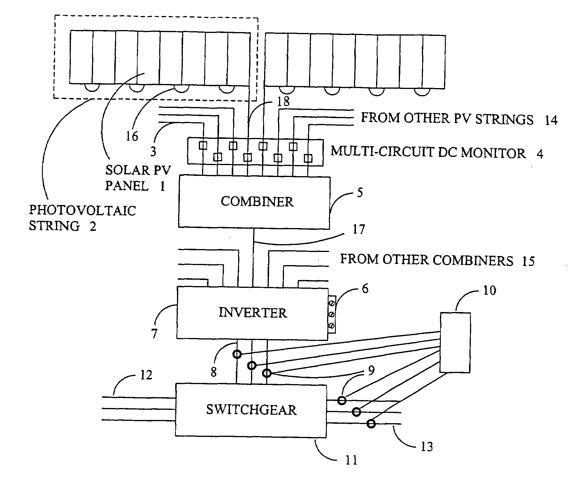
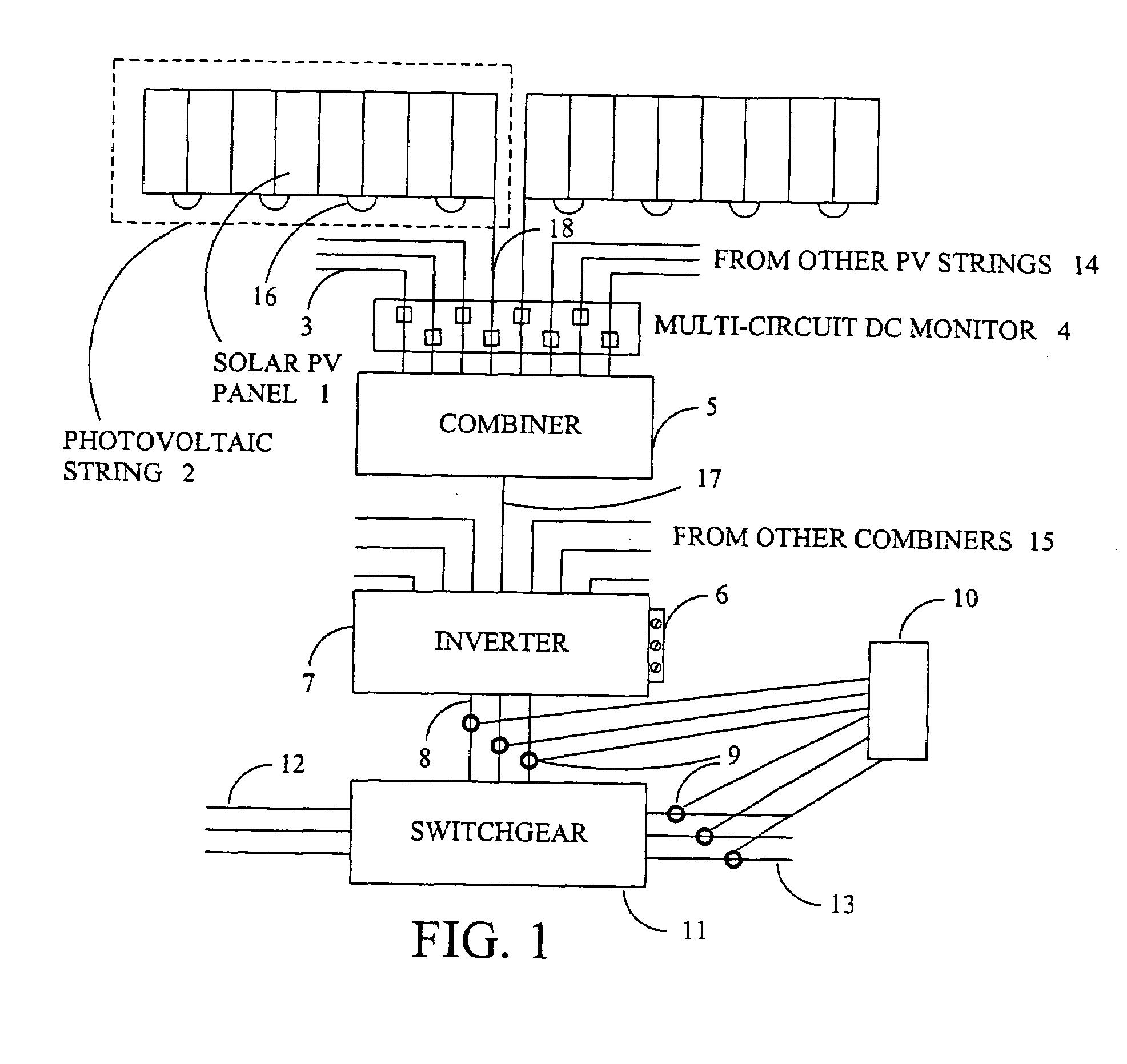
[0015]Many commercial and institutional building owners are installing solar photovoltaic systems to reduce their operating costs by generating electricity when sufficient solar energy is available and, in some cases, to sell power back to the utility when there is excess power available from the solar system. In addition to the potential savings and income generated from the solar system, there are significant incentives available from the utilities and from local, state and federal government entities. Most of these installations are performed by contractors who specialize in solar projects, and these contractors may or may not provide guarantees of performance to the owners or may share in the savings generated. Regardless of who benefits from the installation of the solar generating system, the only way to increase the return on investment (and recover the incentives) is to provide monitoring of operational parameters, both for the system as a whole and its component parts. If t...


PUM


Abstract

A multi-circuit direct current monitor consists of a plurality of Hall Effect current sensors mounted on a printed circuit board oriented to sense the direct current (DC) flow from power generating devices such as solar arrays, output from the Hall Effect sensors connected to an analog to digital (A/D) converter which in turn is connected to a microprocessor. The multi-circuit direct current monitor continuously monitors instantaneous and average current values for each circuit as well as total instantaneous current and average current for all active circuits. The multi-circuit direct current monitor provides continuous communications via Modbus RTU as well as providing alarm outputs if one or more circuits deviates from the average output by a percentage greater than the user specified threshold for a user-defined period of time to detect failed or underperforming power output devices.

Description

CROSS-REFERENCE TO RELATED APPLICATIONS[0001]This application claims the benefit of U.S. Provisional App. No. 60 / 984,497, filed Nov. 1, 2007.BACKGROUND OF THE INVENTION[0002]The present invention relates to a device for monitoring multiple DC electrical currents using sensors and, more particularly, to a device for monitoring performance of multiple solar arrays with the sensors. This is referred to as Multi-Circuit Direct Current Monitor (MCDCM) for purposes of this application.[0003]Many commercial and institutional building owners are installing solar arrays to provide electrical energy that can be used at the facility and, in some cases, sold back to the utility providing power to the facility. There are a number of elements that are monitored in these systems, both to measure the amount of power produced and consumed in the facility and to ensure that the solar panels and arrays are functioning at peak efficiency. A typical large scale (>100 kilowatts) installation has a num...

Claims


Application Information

Patent Timeline
Patent Type & Authority Applications(United States)
IPC IPC(8): G01R19/00G01R15/20G06F19/00
CPCG01R15/202H02S50/10Y02B10/14Y02B10/10Y02E10/50
Inventor LEWIS, JAMES E.HERZOG, STEPHEN E.
Owner OBVIUS HLDG
Why Eureka
Try Eureka