U-clip assembly and method

Inactive Publication Date: 2009-09-10
WEST ROBERT J
View PDF12 Cites 2 Cited by
  • Summary
  • Abstract
  • Description
  • Claims
  • Application Information

AI Technical Summary

Benefits of technology

[0013]It is an object of this invention to provide a new structure and method for forming a U-clip assembly utilizing soft metal wire to join wires used in fishing traps wherein the clips are the typical type having two lateral legs on one side with a medial leg on the other side joined by a crown portion and having a pair of parallel slots, being first and second slots defined in the crown portion of each U-clip. A plurality of U-clips, when aligned, have their respective first and second slots aligned along a longitudinal axis with one another so that first and second soft metal wires, such as soft aluminum wire, can be inserted in each aligned first slot and a second soft metal wire can be inserted in each aligned second slot, respectively, and both compressed on the tops of each wire, causing the first and second soft metal wires to be deformed and urged outward against the sides of their respective slots in which they are positioned. In a preferred embodiment the soft metal wire can be a 1350 alloy or 1100 alloy of 99%-99.5% pure aluminum in a 0 temper state. The use of such soft metal wire is critical to the present invention. The diameter of the soft metal wire can be the same or slightly wider than the diameter of the slots. The use of a soft metal wire also has an advantage when these clips are used in the bedding industry where heating can sometimes be necessary for tempering. A plastic cord, such as nylon, might melt as it has a far lower melting temperature than metal wire. Soft metal wire, when compressed from the top into a slot, expands against the sides of the slot and is forced tightly therein as the sides of the soft metal wire are pushed outward, contacting not only on the bottom of the slot, but also urging against its sides as well. Further, since such soft metal wire is not resilient as is the plastic cord of the prior art, it stays in its compressed, expanded position within the slot.
[0014]It is a further object of this invention to provide a clip assembly that is compatible with the requirements of the fishing industry. Soft metal wire can be chosen of a type compatible with preventing electrolysis when the clips are used in the fishing industry. The clips used in the fishing industry have legs that spread outward

Problems solved by technology

Further, since such soft metal wire is not resilient as is the plastic cord of the prior art, it stays in its compressed, expanded position within the slot.
However, since lobster tr

Method used


Image

  • U-clip assembly and method
  • U-clip assembly and method
  • U-clip assembly and method

Examples


Example

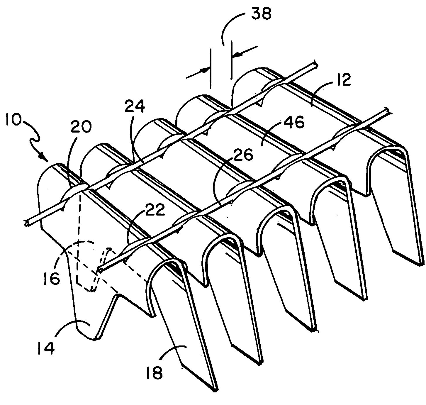
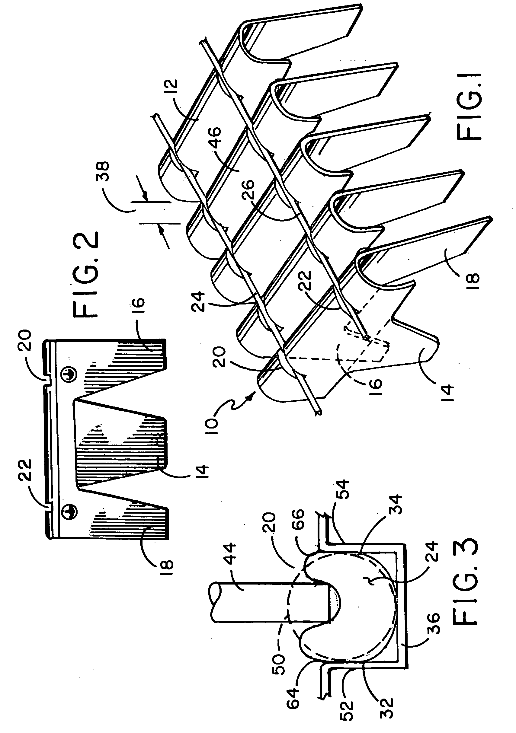
[0022]FIG. 1 illustrates a rear perspective view of a plurality of U-clips 12, forming a U-clip assembly 10 which is held together by a first and second soft metal wires 24 and 26 which are disposed, respectively, within first slot 20 and second slot 22 which slots are defined in the tops of each U-clip 12. Each U-clip 12 also referred to as clip 12 has first and second transversely spaced legs 16 and 18 in the front and a medial leg 14 in the rear. The front legs and rear leg are spaced apart from one another at an angle, spreading apart at the bottoms thereof so that crown portion 46 of each clip in a row of clips is spaced apart a distance 38 from the crown portion of the adjacent clip. First and second soft metal wires 24 and 26 are shown disposed, respectively, within first and second slots 20 and 22 of each clip, such slots also seen in the front view of clip 12 of FIG. 2. First slot 20 and second slot 22 each has a base 36. The collated assembly of clips, as seen in FIG. 1, a...


PUM

PropertyMeasurementUnit
Lengthaaaaaaaaaa
Widthaaaaaaaaaa
Softnessaaaaaaaaaa

Abstract

A structure and method for forming a U-clip assembly made of a plurality of U-clips arrayed in a continuous abutting relation, each U-clip having first and second slots defined in its crown portion with first and second soft metal wires positioned, respectively, in such first and second slots, such soft metal wire forming a shallow U shape between adjacent crown portions, such first and second soft metal wires being compressed within their slots to expand within such slots for contacting and urging against the sides and bottom of each slot and being retained therein, such soft metal wire and its shallow U shape between adjacent crown portions allowing the U-clip assembly to maintain a non-curved shape and to be substantially flat in configuration.

Description

[0001]This application claims priority and benefit of a provisional patent application entitled U-Clip Assembly and Method, Ser. No. 61 / 068,280 filed Mar. 7, 2008, now pending.BACKGROUND OF THE INVENTION[0002]1. Field of the Invention[0003]The present invention relates to a U-clip assembly for insertion into an application tool and more particularly relates to a U-clip assembly comprised of a plurality of U-clips, each having a pair of slots defined in the crown of each, which clips are aligned in a row with soft metal wire positioned in the slots for retaining the U-clips in such row.[0004]2. Description of the Prior Art[0005]U-clips or clips have long been used in the prior art for the assembly and retention of pairs of wires. There is a body of this art which relates to furniture, spring retention and retention of wires in automobile seats and another body of art where the U-clips are somewhat different for the retention of wires in traps, such as lobster traps. The term “U-clip”...

Claims


Application Information

Patent Timeline
IPC IPC(8): A44B21/00B21D39/00A44B99/00
CPCB21D53/36Y10T24/344Y10T29/49874F16B15/08
Inventor WEST, ROBERT J.
Owner WEST ROBERT J
Why Eureka
Try Eureka