Magazine type clipping device

a clipping device and clipping device technology, applied in the field of endoscopic clipping devices, can solve the problems of unstable connection, twisting or distortion of the clips to be used, and the conventional clipping device involves a rather bothersome operation, so as to achieve smooth clipping operation, maintain the connected state of the loaded clips, and high precision

Inactive Publication Date: 2009-09-10
FUJIFILM CORP
View PDF4 Cites 3 Cited by
  • Summary
  • Abstract
  • Description
  • Claims
  • Application Information

AI Technical Summary

Benefits of technology

[0006]It is an object of the present invention to eliminate the above-mentioned problems in the related art and to provide a magazine type clipping device which is capable of reliably maintaining the connected state of the clips loaded in such a state, which is free from a fear of damaging the sheath inner wall, and which can perform clipping operation smoothly and with high precision. Another object of the present invention is to provide a magazine type clipping device capable of effecting the clamping and separation of (canceling of connection) the foremost clip by a series of operations in one direction.

Problems solved by technology

In this way, the convention clipping device involves a rather bothersome operation.
Thus, the connection is rather unstable, and disconnection may occur at the time of insertion into the endoscope or when the devices is passed through a curved portion, or there is the possibility of an excessive force being applied to the connecting portion to cause twisting or distortion in the clips to be used.
Further, there is a fear of projections or corner portions of the clips at the connecting portion damaging the inner wall of the sheath when a curved portion is passed through.
Thus, the clip pulling load is unnecessarily large, and there is a fear of the sheath inner wall being damaged.
However, this connected portion involves play, and hence wobble is generated at the time of advancing / retreating movement, thus giving the operator an unstable feel, and further, a precise control of the advancing / retreating movement is rather difficult to perform.

Method used


Image

  • Magazine type clipping device
  • Magazine type clipping device
  • Magazine type clipping device

Examples


embodiment 1

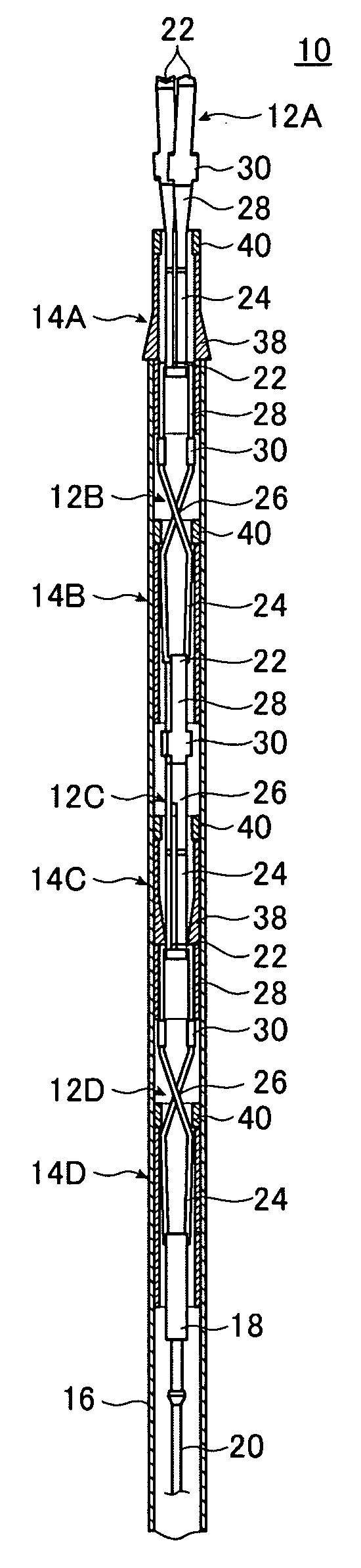
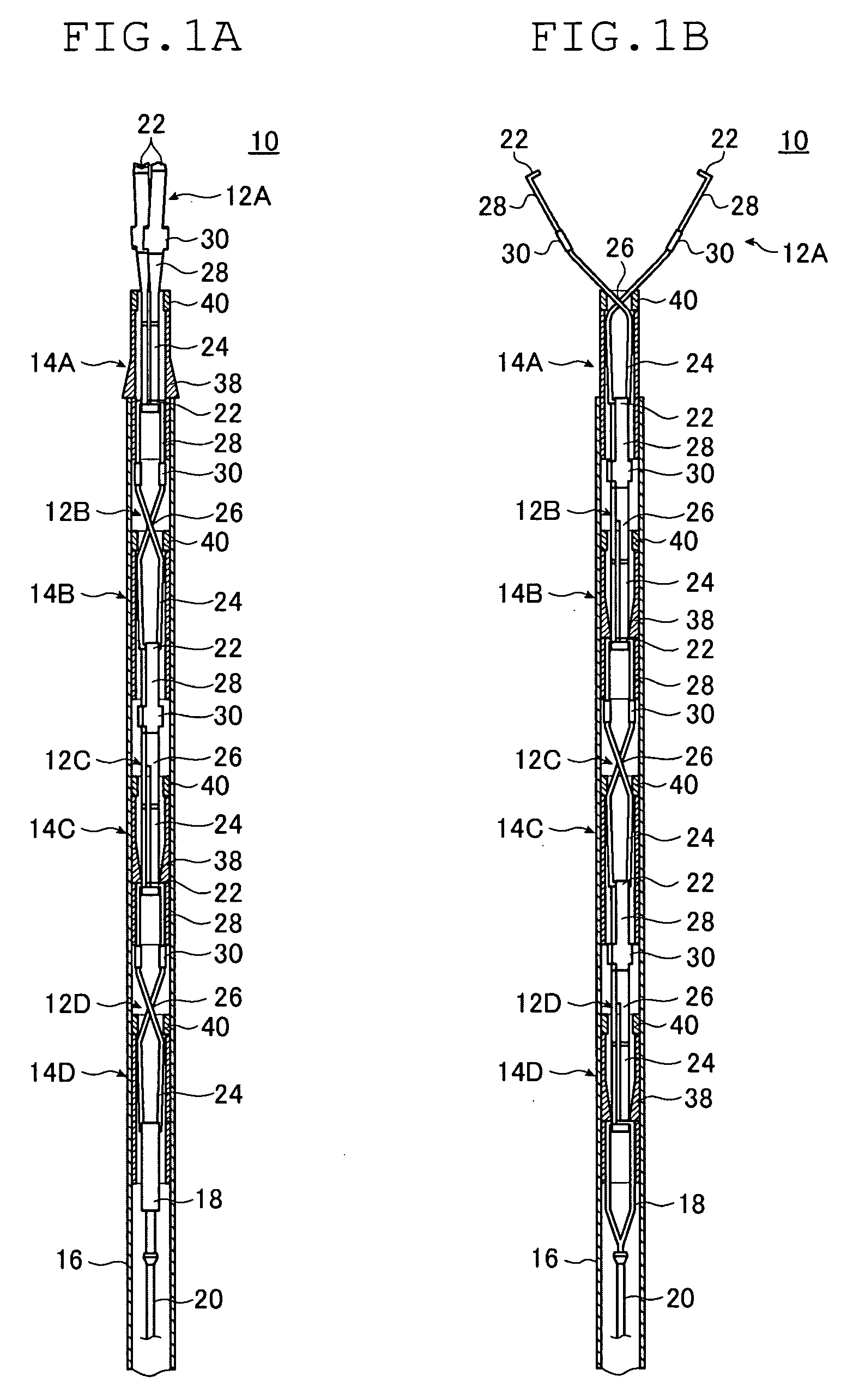
[0032]FIGS. 1A and 1B are sectional views of a clipping device 10 according to Embodiment 1 of the present invention, and FIG. 1B is a diagram as seen from an angle differing from FIG. 1A by 90 degrees.

[0033]The clipping device 10 is a magazine type clipping device in which clips can be used in succession and which has a plurality of clips 12 (12A, 12B, 12C, and 12D), a dummy clip 18 connected to the rearmost clip 12D, a manipulating wire 20 connected to the dummy clip, and connection rings 14 (14A, 14B, 14C, and 14D) covering the engagement portions of the adjacent clips 12 to maintain the clips 12 in the connected state, with those components being fitted into a sheath 16. FIGS. 1A and 1B illustrate an initial state immediately before the start of clipping manipulation by the foremost clip 12.

[0034]One clip 12 and one connection ring 14 corresponding to the clip 12 form one endoscopic bleeding stop clip member, and the clipping device 10 includes a plurality of such bleeding stop ...

embodiment 2

[0091]A magazine type clipping device according to Embodiment 2 of the present invention is described. Embodiment 2 differs from Embodiment 1 described above in the construction of the connection ring. Otherwise, it is basically of the same component construction and operation as Embodiment 2.

[0092]FIGS. 7A through 7C are a front view, a sectional view, and a bottom view of a connection ring 50 according to Embodiment 2. The connection ring 50 is of the same structure as the connection ring 14 of Embodiment 1 except that a retaining portion 142 has a third region 136 continuous with a second region 134. That is, the connection ring 50 is composed of the metal clamping portion 40 and the resin retaining portion 142, and the retaining portion 142 has the first region 32 retaining the preceding clip 12, the second region 134, which is a connection maintaining region retaining the succeeding clip 12 connected to the preceding clip 12, and the third region 136, which is a connection canc...

embodiment 3

[0122]Instead of the connection rings 14 of the clipping devices 10 of Embodiment 1, it is possible to use a connection ring 60 as illustrated in FIGS. 11A through 11C.

[0123]The connection ring 60 is of the same construction as the connection ring 14 of Embodiment 1 except that two slits 62 are formed in a second region 234 of a retaining portion 242. That is, the connection ring 60 includes the metal clamping portion 40 and the resin retaining portion 242, and the retaining portion 242 has a first region 32 and a second region 234, with the second region 234 having the slits 62 cut from the proximal end thereof at positions opposed to each other.

[0124]The slits 62 are cutouts of a certain width open on the proximal end side of the connection ring 60 and substantially parallel to the axis of the connection ring 60. It is desirable for the slits 62 to be provided at circumferential positions of the connection ring 60 different from those of the skirt portions 38. Further, it is desir...


PUM


Abstract

A magazine type clipping device comprises: clips loaded into a sheath while being engaged with other clips longitudinally connected together; at least one connection ring fitted into the sheath so as to be capable of advancing and retreating, and covering an engagement portion of the clips to maintain the clips in a connected state; and a manipulating wire connected to a rearmost clip and adapted to pull a clip row formed of the plurality of clips, each clip having a pair of openable / closable claw portions and a tail portion, the connection ring having a connection maintaining region retaining a pair of clips engaged with each other, with the pair of claw portions of a succeeding clip being closed while holding the tail portion of a preceding clip.

Description

BACKGROUND OF THE INVENTION[0001]The present invention relates to an endoscopic clipping device used for stopping bleeding, closing a puncture, etc. in a living body or the like and, in particular, to a magazine type clipping device which allows a plurality of clips to be used in succession.[0002]An endoscopic clipping device causes a clip to protrude from the forward end of an endocope inserted into a living body to pinch a bleeding portion or a portion to be treated after the removal of the lesion tissue with the clip, thereby stopping the bleeding or closing the puncture. In a conventionally used endoscopic clipping device, a single clip is detachably attached to the forward end of a manipulating wire, and each time clipping is performed, the entire sheath is drawn out of the endoscope, and the sheath is loaded with the next clip before being inserted into the endoscope again for the next clipping. In this way, the convention clipping device involves a rather bothersome operation...

Claims


Application Information

Patent Timeline
Patent Type & Authority Applications(United States)
IPC IPC(8): A44B21/00A44B99/00
CPCA61B17/1227A61B17/1285A61B2017/0034Y10T24/4453A61B2019/304A61B2019/4857A61B2017/2911A61B2090/034A61B2090/0811
Inventor CUI, SHENGFUIIDA, TAKAYUKI
Owner FUJIFILM CORP
Why Eureka
Try Eureka