System and method for the treatment of insomnia
a technology for insomnia and insomnia, applied in the field of insomnia treatment devices and methods, can solve the problems of limiting the effectiveness of prior treatments for insomnia, high cost and time consumption of behavioral therapy techniques, and accelerating the onset of sleep. , to achieve the effect of maintaining the patient's sleep state and accelerating the onset of sleep
- Summary
- Abstract
- Description
- Claims
- Application Information
AI Technical Summary
Benefits of technology
Problems solved by technology
Method used
Image
Examples
second embodiment
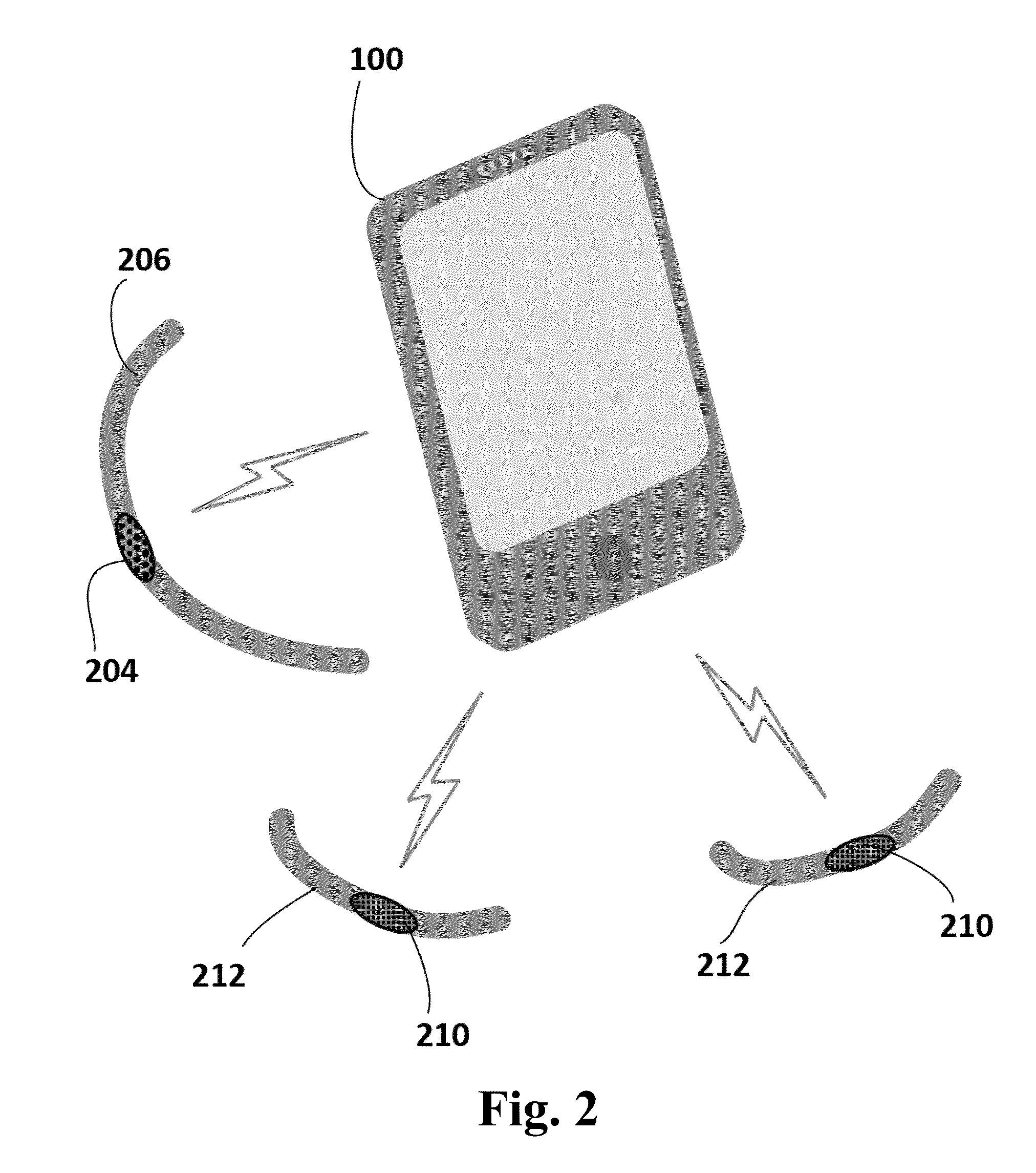
[0075]FIG. 2 is a perspective view of the present invention. In this embodiment a portable, battery powered controller 100 as previously described in FIG. 1 is coupled to two portable, battery powered, patient worn modules 210 and to one portable, battery powered, patient worn module 204.
[0076]The patient worn modules 210 each contain a processor (not visible), which is coupled to one or more wireless communication mechanisms (not visible), a stimulator (not visible) and one or more physiological sensors (not visible). The stimulator may optionally comprise an electroactive polymer, which responds to an induced electrical current by contracting, and which, when so activated, causes a tactile stimulation when coupled to a patient. The physiological sensors may optionally comprise one or more actimetry sensors, which detect gross motor movement when coupled to a patient. The processor in the patient worn modules 210 may periodically process data from the actimetry sensors and transmit...
third embodiment
[0091]FIG. 3 is a perspective view of the present invention. In this embodiment a portable, battery powered controller 100 as previously described in FIG. 1 is coupled to two portable, battery powered, patient worn modules 310 and to two portable, battery powered, patient worn modules 302.
[0092]The patient worn modules 310 each contain a processor (not visible), which is coupled to one or more wireless communication mechanisms (not visible), a stimulator (not visible) and one or more physiological sensors (not visible). The stimulator may optionally comprise one or more transcutaneous electrical nerve stimulators (TENS), which produce a mild electrical current, and which, when activated, cause a stimulation of the patient's nerves when coupled to a patient. The physiological sensors may optionally comprise one or more heart rate sensors, which detect the patient's heart rate when coupled to a patient. The processors in the patient worn modules 310 may periodically process data from ...
fourth embodiment
[0122]FIG. 4 is a perspective view of the present invention. In this embodiment a portable, battery powered controller 100 as previously described in FIG. 1 is coupled to two portable, battery powered, patient worn modules 302 and to one portable, battery powered, patient worn module 402.
[0123]The patient worn modules 302 are the same as described previously in FIG. 3.
[0124]The patient worn modules 402 each contain a processor (not visible), which is coupled to one or more wireless communication mechanisms (not visible), and a stimulator (not visible). The stimulator may optionally comprise multiple light emitting diodes (LEDs) arranged in a horizontal array, which when energized create a visual stimulation when coupled to a patient.
[0125]The patient worn module 402, and the patient worn modules 302, may be optionally attached to a single adjustable belt 404.
[0126]The controller 100 is optionally coupled to the two patient worn modules 302 through the wireless communication mechanis...
PUM
 Abstract
Description
Claims
Application Information
 - R&D
- Intellectual Property
- Life Sciences
- Materials
- Tech Scout
- Unparalleled Data Quality
- Higher Quality Content
- 60% Fewer Hallucinations
Browse by: Latest US Patents, China's latest patents, Technical Efficacy Thesaurus, Application Domain, Technology Topic, Popular Technical Reports.
© 2025 PatSnap. All rights reserved.Legal|Privacy policy|Modern Slavery Act Transparency Statement|Sitemap|About US| Contact US: help@patsnap.com


