Evaporated fuel treatment device

A technology for evaporating fuel and processing device, applied in the field of evaporating fuel processing device, can solve the problems of large airflow resistance and inability to ensure air permeability, and achieve the effects of reducing cost and reducing position changes

Inactive Publication Date: 2014-01-01
MAHLE FILTER SYST JAPAN CORP
View PDF9 Cites 3 Cited by
  • Summary
  • Abstract
  • Description
  • Claims
  • Application Information

AI Technical Summary

Problems solved by technology

Therefore, there is a concern that the airflow resistance becomes too large to ensure the necessary air permeability

Method used


Image

  • Evaporated fuel treatment device
  • Evaporated fuel treatment device
  • Evaporated fuel treatment device

Examples


Embodiment Construction

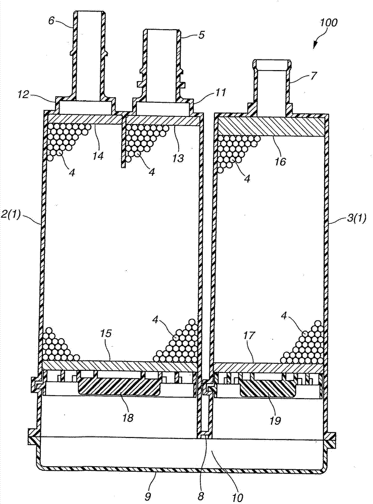
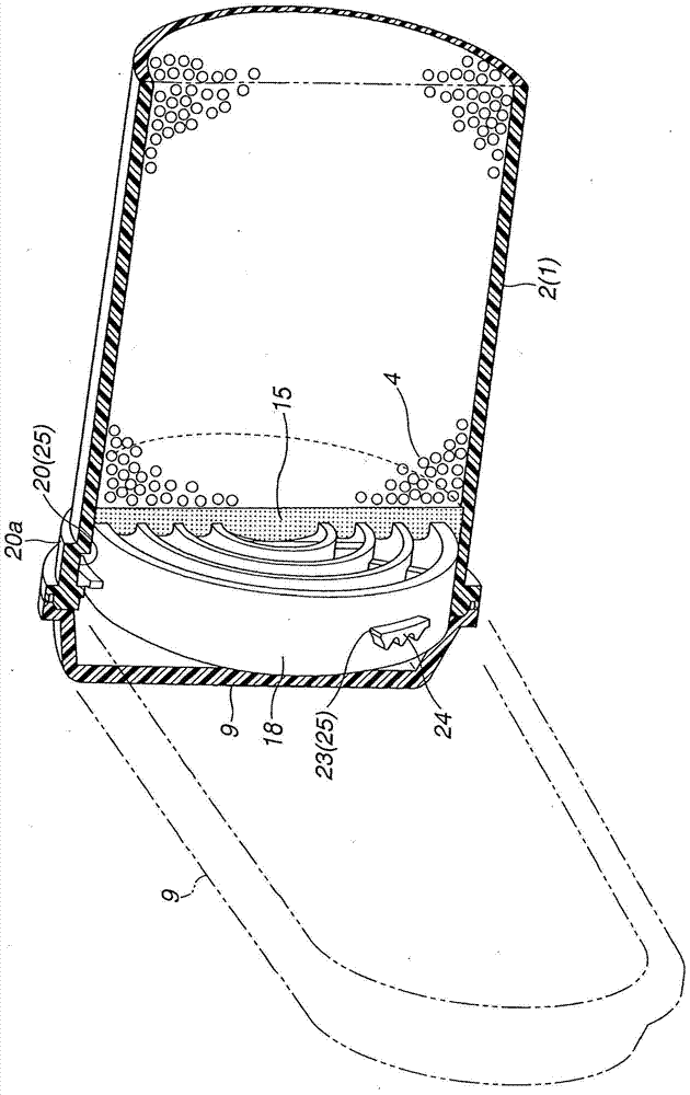
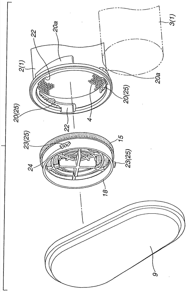
[0035] refer to Figure 1 to Figure 5 , an evaporated fuel processing device (hereinafter simply referred to as a canister) according to a first embodiment of the present invention will be explained hereinafter. figure 1 A cross-section of a so-called two-chambered tank is shown as a whole. Figure 2 to Figure 5 show figure 1 Details of the tank shown in the construction.

[0036] Such as figure 1 As shown in , the tank 100 includes a sealed casing 1 and an adsorbent 4 filled in the casing 1 . Adsorbent 4 is granular activated carbon. The granular activated carbon can be generally in the form of granular carbon particles or pulverized carbon particles. The housing 1 comprises a filling port 5 , a purge port 6 , an atmospheric vent 7 and a cover part 9 . A cover member 9 is arranged at one end of the housing 1 . A filling port 5 , a purge port 6 and an atmospheric vent 7 are arranged at the other end of the housing 1 .

[0037] Specifically, the housing 1 includes two c...


PUM


Abstract

An evaporated fuel treatment device including a cylindrical casing body, a granular adsorbent filled in the casing body, an air permeable member stacked on the granular adsorbent, a retainer member stacked on the air permeable member, and a tooth-shaped positioning retention mechanism disposed between an inner circumferential surface of the casing body and an outer circumferential surface of the retainer member. The tooth-shaped positioning retention mechanism allows the retainer member to hold the air permeable member in a compressively deformed state, enables positioning and retention of the retainer member in an optional position relative to the casing body in a pushing direction of the retainer member, and inhibits displacement of the retainer member in a removal direction of the retainer member.

Description

technical field [0001] The present invention relates to an evaporated fuel treatment device (also referred to as a canister) for adsorbing fuel evaporated in a fuel tank of an automobile to allow combustion of the fuel in the engine during operation of the engine. Background technique [0002] For example, so-called canisters using activated carbon as an adsorbent are known as conventional evaporated fuel treatment devices. There are flow paths in the tank through which evaporated fuel and atmospheric air are allowed to flow. Evaporated fuel from the fuel tank is temporarily adsorbed in activated carbon in the tank. On the other hand, during operation of the engine, atmospheric air is introduced into the tank using engine negative pressure, and evaporated fuel adsorbed in activated carbon is desorbed therefrom. The evaporated fuel thus desorbed is sucked into the engine, thereby being used for combustion of the evaporated fuel. [0003] In addition, as described in Japane...

Claims


Application Information

Patent Timeline
Patent Type & Authority Applications(China)
IPC IPC(8): B01D53/04F02M25/08
CPCB01D53/0415F02M25/0854B01D2259/4516
Inventor 荒濑雄治吉田博行堀松俊宣
Owner MAHLE FILTER SYST JAPAN CORP
Why Eureka
Try Eureka