
Drainage System For A Floor

a draining system and floor technology, applied in the field of floor construction, can solve the problems of high maintenance costs of these systems, wood floors, especially older ones, tend to squeak in certain places, and are more expensive to construct, so as to speed up the draining time and eliminate the accumulation of rainwater

Inactive Publication Date: 2009-09-10
SPIGNESI LEO
View PDF24 Cites 19 Cited by
  • Summary
  • Abstract
  • Description
  • Claims
  • Application Information

AI Technical Summary

Benefits of technology

[0012]These, and other, objects are achieved by a drain system for draining water from a Lanai floor to eliminate rainwater build-up on lanai floors and speed-up draining time on such floors. The device is attached to the edge of the Lanai floor and acts as a scupper. As used herein, the term “scupper” means a drain at the edge of a deck exposed to the weather, for allowing accumulated water to drain away into, for example, bilges.

Problems solved by technology

Maintenance of these systems can be very expensive however, requiring the opening of concrete or other fixed structures.
Wood floors, particularly older ones, will tend to squeak in certain places.
Concrete floors are usually so solid they do not have this problem, but are also much more expensive to construct, and much heavier, resulting in further requirements regarding the structure of the building.
In cities, and even some more rural settings, personal privacy is often difficult to maintain.
Additionally, these encroachments by passersby can occur at lake homes, at homes along waterways or rivers and even at restaurants with outdoor eating areas.
These items are often subject to rain or other such precipitation which may tend to leave moisture on the floor.
The metal track, however, acts as a barrier so that water does not flow away from the floor such that many homeowners have found it difficult and onerous to remove such water and moisture.

Method used


Image

  • Drainage System For A Floor
  • Drainage System For A Floor

Examples


Embodiment Construction

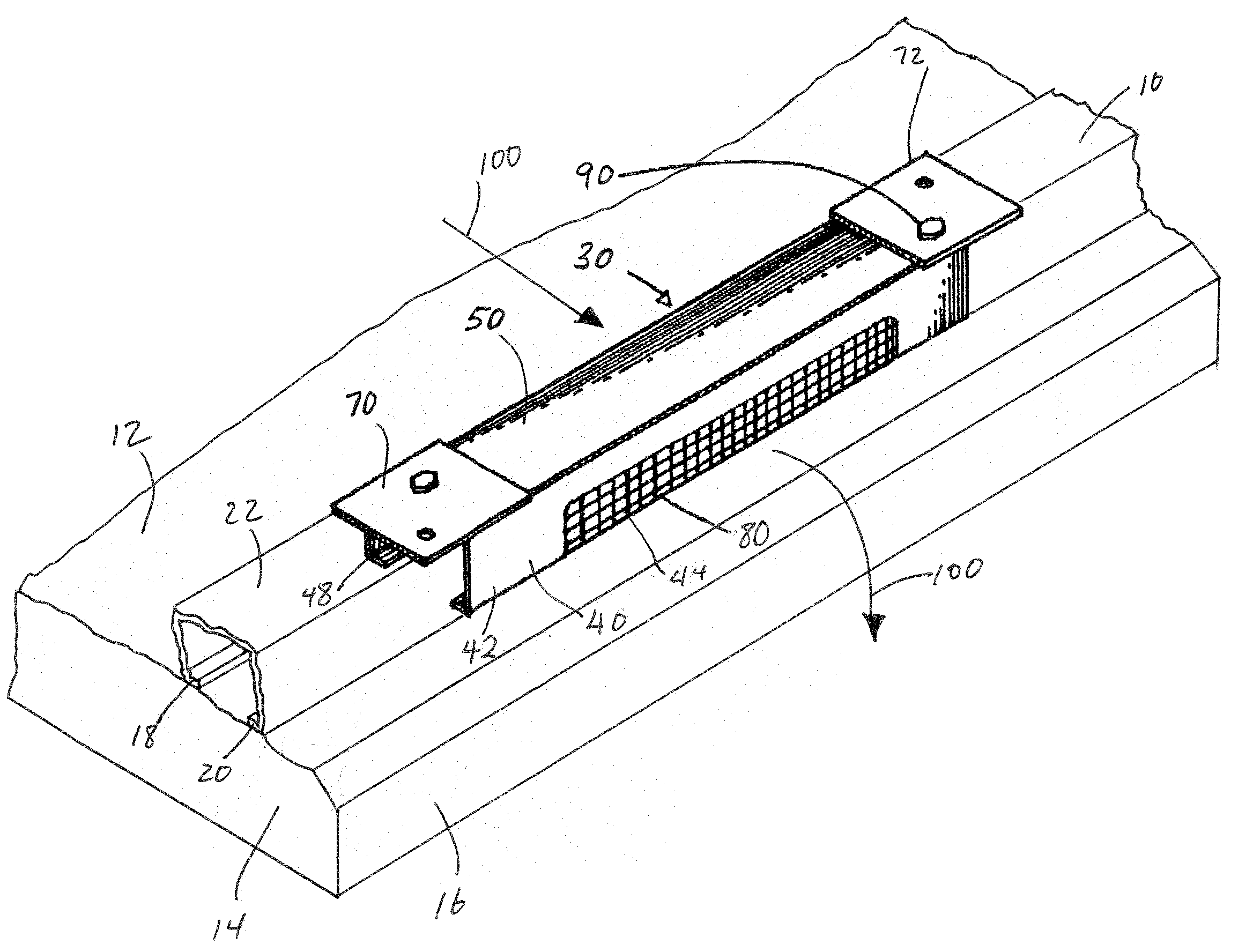
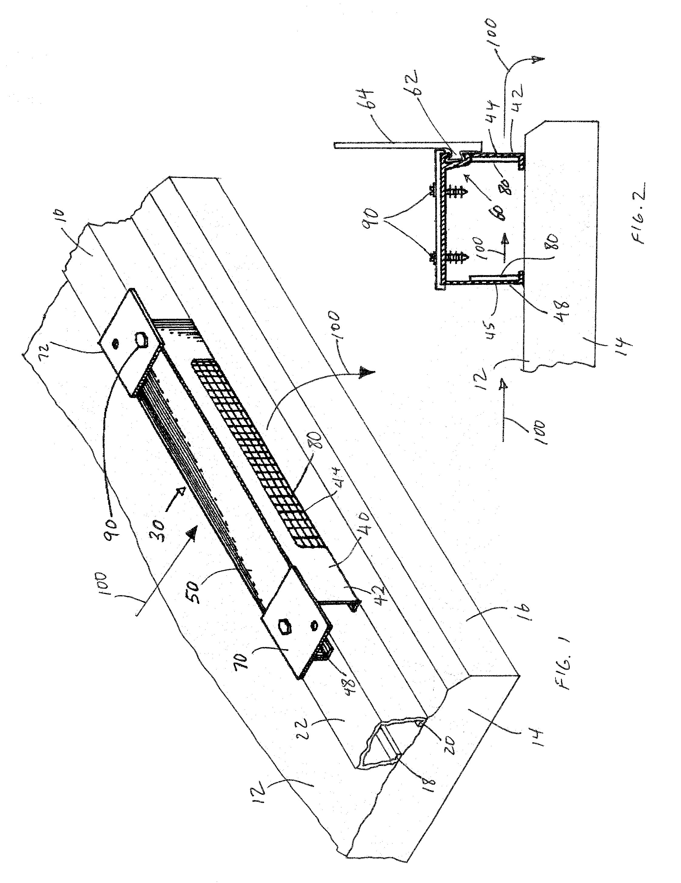
[0018]Referring to FIG. 1, it can be understood that the present invention is embodied in a scupper unit 30 adapted to incorporate into a portion of a metal track 10 mounted on top surface 12 of floor 14 adjacent to its 16. The track 10 has a U shape with two legs 18 and 20 adapted to anchor to the floor 14. The track 10 may be made of aluminum, which substantially resists corrosion due to water. The metal track 10 has a top surface 22 adapted to support a bottom of an enclosure to substantially prevent the bottom of the enclosure from water damage. The floor may be Lanai floor formed from concrete.

[0019]To allow water to flow towards the edge of the floor 14, the scupper unit 30 is incorporated into a portion of the metal track 10. The scupper unit 30 includes a U-shaped housing 40 which can be formed of plastic and has a first leg 42 with an opening 44 defined therein, a second leg 48 has an opening 45, and a bight section 50 which connects the first and second legs together. Each...


PUM


Abstract

A drain system for draining water from a lanai floor to eliminate rainwater build-up on lanai floors and speed-up draining time on such floors. The device is attached to the edge of the Lanai floor and acts as a scupper.

Description

TECHNICAL FIELD OF THE INVENTION[0001]The present invention relates to the general art of flooring, and to the particular field of accessories for draining a floor.BACKGROUND OF THE INVENTION[0002]In architecture, a floor is generally the lower horizontal surface of a room, and / or the supporting structure underneath it. It also commonly refers to flooring, or a wall-to-wall floor covering, which forms the decorative surface of the floor. The various levels in a building are also called floors, levels or stories. For example, “ground floor”, “main floor”, “first story”, “mezzanine floor,” etc.[0003]A ground-level floor can be soil, or be built on a ‘slab’, such as a concrete slab. Floors above may be built on beams or joists or use structures like hollow core slabs. Ground-level slab floors are prepared for pouring by grading the base material so that it is flat, and then spreading a layer of sand and gravel. A grid of rebar is usually added to reinforce the concrete, especially if i...

Claims


Application Information

Patent Timeline
Patent Type & Authority Applications(United States)
IPC IPC(8): E04F17/00E04B1/70
CPCE04D13/0431E04F17/00E04D2013/0463
Inventor SPIGNESI, LEO
Owner SPIGNESI LEO
Learn More